
Data transmission method, data transmission apparatus, and data transmission system

Inactive Publication Date: 2009-12-08
NTT DOCOMO INC
View PDF15 Cites 1 Cited by
  • Summary
  • Abstract
  • Description
  • Claims
  • Application Information

AI Technical Summary

Benefits of technology

[0010]Such being the case, in order to solve the above-described problems, it is an object of the invention to provide a data transmission method, a data transmission apparatus, and a data transmission system which make it possible to improve the transmission efficiency of a channel during multilink communication and to reduce the load of processing.
[0014]In those aspects of the invention, both or either of the data volume and the pattern of data division can be controlled based on a record of performance of transmission on each of the transmission channels. Therefore, when there is a change in the record of performance of transmission of a transmission channel, both or either of the data volume and the pattern of data division can be controlled based on a record of performance of transmission after the change. It is also possible to improve transmission efficiency of a channel in multilink communication and to reduce the load of processing.
[0016]In this aspect of the invention, both or either of the data volume and the pattern of data division can be controlled based on the number of transmission channels used as the plurality of transmission channels. Therefore, when there has occurred a change in the number of transmission channels, both or either of the data volume and the pattern of data division can be controlled based on the number of transmission channels after the change. It is also possible to improve transmission efficiency of a channel in multilink communication and to reduce the load of processing.
[0018]In this aspect of the invention, since the timing for changing both or either of the data volume and the pattern of data division is controlled based on the volumes of data transmitted by the transmission channels, both or either of the data volume and the pattern of data division can be reliably changed even when there has occurred a delay between the transmission channels.
[0020]In those aspects of the invention, both or either of the data volumes and the pattern of data division can be controlled with reference to both or either of data volumes and patterns of data division which are defined in advance in accordance with a record of performance of transmission. As a result, data to be transmitted by a transmission channel is not required to include in itself information indicating the data volume stored therein, and the transmission efficiency of the channel can therefore be improved during multilink communication. Further, both or either of a data volume and a pattern of data division in accordance with a change in the number of transmission can be readily altered by referring to both or either of the data volumes and patterns of data division defined in advance. This makes it possible to change both or either of the data volume and the pattern of data division easily and to thereby reduce the load of processing.
[0024]In this aspect of the invention, since data can be transmitted during multilink communication in a data volume that is determined taking into account the buffer capacities of both of the terminals, the data can be more reliably transmitted.

Problems solved by technology

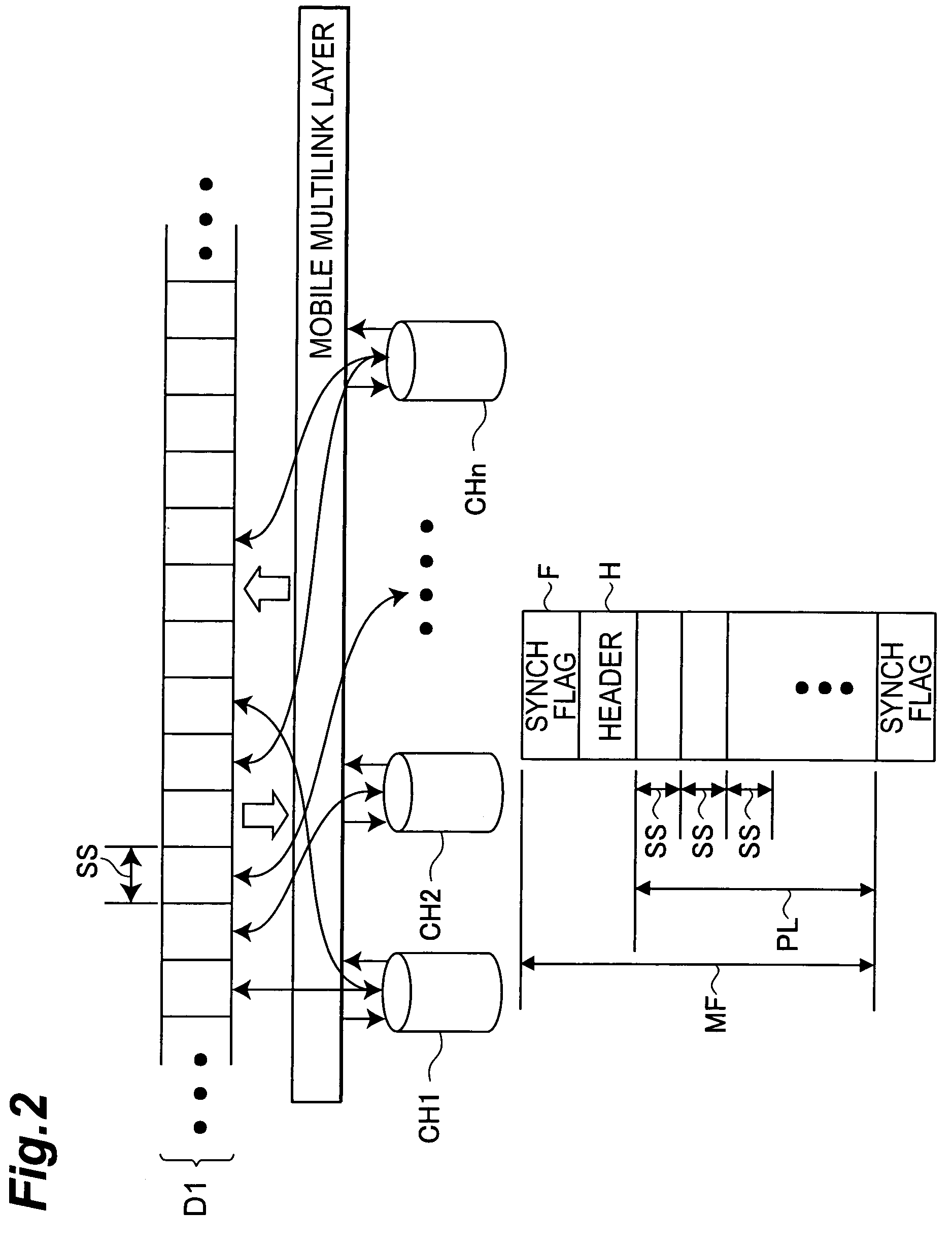
Therefore, when the size of the payload or the contents of SS and SPF are frequently changed depending on the state of transmission of the channel, a problem has arisen in that transmission efficiency of the channel is reduced by the addition of the SS and SPF values to the header information.
This has necessitated a complicated process and resulted in the problem of an increase in the load of processing.

Method used


Image

  • Data transmission method, data transmission apparatus, and data transmission system
  • Data transmission method, data transmission apparatus, and data transmission system
  • Data transmission method, data transmission apparatus, and data transmission system

Examples


Embodiment Construction

[0038]Preferred embodiments of an apparatus according to the invention will now be described with reference to the drawings. In each of the figures, the same element is indicated by the same reference numeral to avoid duplication of description.

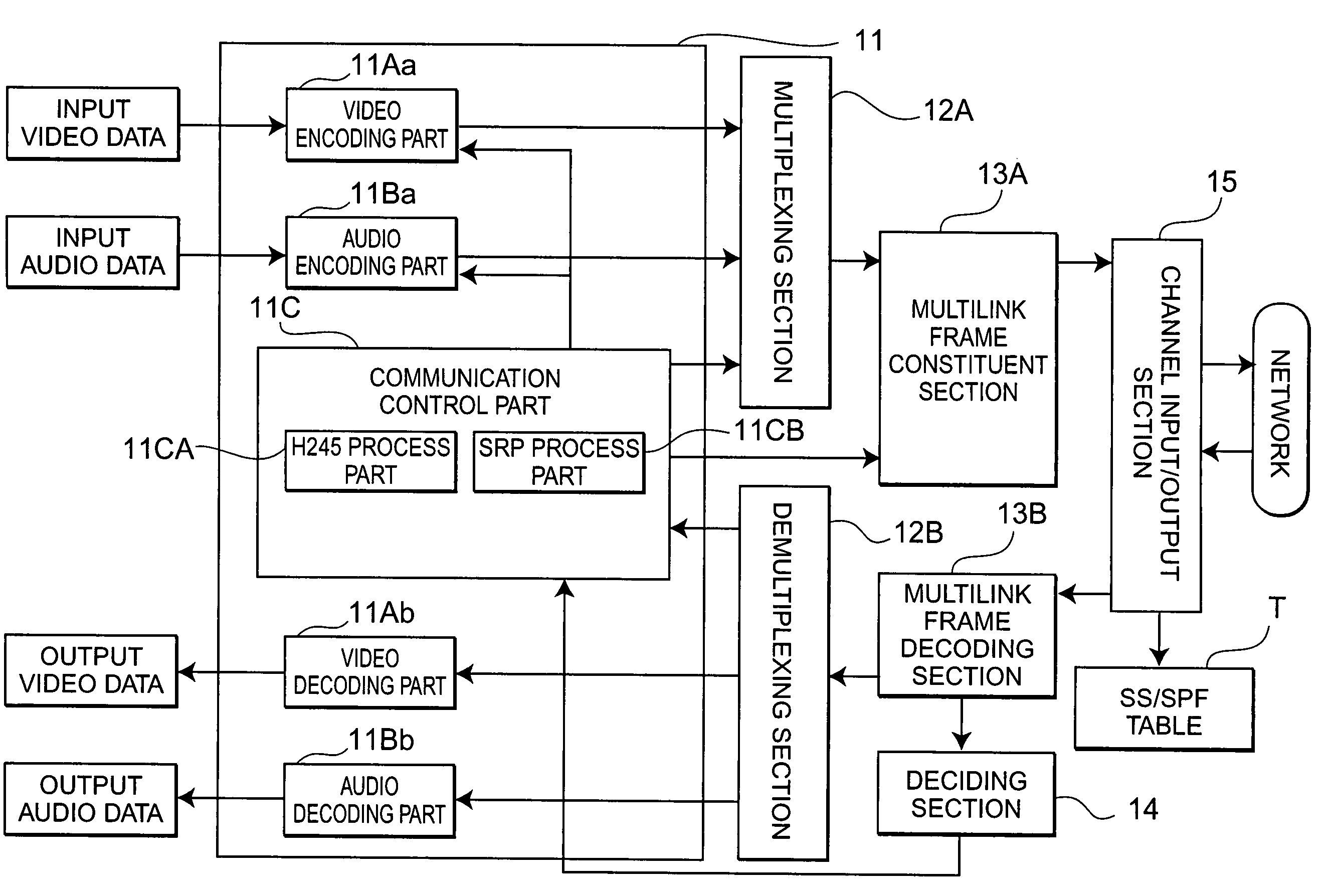
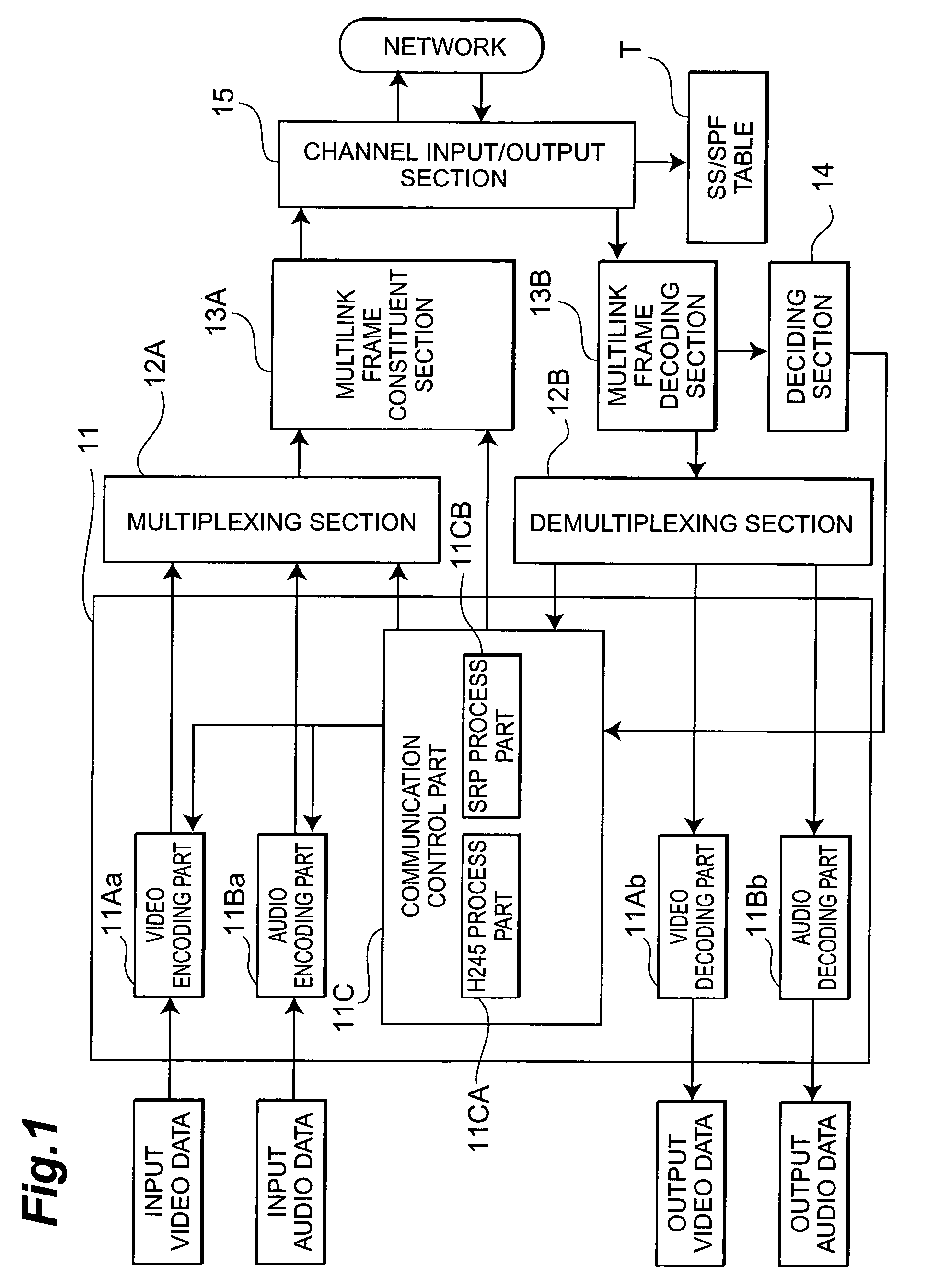
[0039]First, an embodiment of the invention will be described. FIG. 1 is a view illustrating an exemplary functional arrangement of a data transmission apparatus 1 in the present embodiment. As shown in FIG. 1, the data transmission apparatus 1 has a data input / output section 11, a multiplexing section 12A, a demultiplexing section 12B, a multilink frame constituent section 13A, a multilink frame decoding section 13B, a deciding section 14, and a channel input / output section 15. An example of such a data transmission apparatus 1 is a multi-media communication terminal used in a television conference system or visual telephone system. The data transmission apparatus 1 in the present embodiment adopts Recommendation H. 324 Annex H which has bee...


PUM


Abstract

A system for improving the transmission efficiency of channels involved in multilink communication and reducing the load of processing. A first data transmission apparatus changes the number of transmission channels involved in multilink communication from “x” to “y”, acquires SS (sampling size) and SPF(samples per frame) associated with the number of transmission channels “y” from an SS / SPF table, generates multilink frames based on the acquired SS and SPF, and transmits them to a second data transmission apparatus. When it is detected that the number of transmission channels has been changed from “x” to “y”, the second data transmission apparatus acquires the SS and SPF associated with the number of transmission channels “y” from the SS / SPF table, generates multilink frames based on the acquired SS and SPF, and transmits them to the first data transmission apparatus.

Description

BACKGROUND OF THE INVENTION[0001]1. Field of the Invention[0002]The present invention relates to a data transmission method, a data transmission apparatus, and a data transmission system.[0003]2. Related Background Art[0004]Recommendation Series H.32x standardized by ITU-T (International Telecommunication Union-Telecommunication Standardization Sector) has been known as a real-time video communication method for visual telephones. According to this method, plural items of input data such as video data and audio data are combined into one item of data which is then communicated. Various expansion models are defined in Recommendation Series H.32x. In one of the recommendations, i.e., Recommendation H.324 Annex H, a definition is made on multilink communication in which one item of data is transmitted using a plurality of links (channels). For example, techniques associated with the recommendation H.324 Annex H are disclosed in an article titled “ITU-T Recommendation on CD-ROM”, Disc-2...

Claims


Application Information

Patent Timeline
IPC IPC(8): H04J3/04H04L25/14H04L29/00H04L29/08
CPCH04L25/14
Inventor KOBAYASHI, MITSURUYAMAGUCHI, HIROYUKIADACHI, SATORUSUGIMOTO, KAZUOKATO, SADAATSU
Owner NTT DOCOMO INC
Learn More