Vehicle front structure

Active Publication Date: 2011-12-22
TOYOTA JIDOSHA KK
View PDF39 Cites 18 Cited by
  • Summary
  • Abstract
  • Description
  • Claims
  • Application Information

AI Technical Summary

Benefits of technology

[0021]According to the aforementioned construction, at least one of the front inflection portion and the rear inflection portion is formed by connecting the ridge lines for transmitting a load input via the mount member. Thus, the load input via the mount member is guided to the front inflection portion and the rear inflection portion and hence can be reliably transmitted. Accordingly, the front inflection portion and the

Problems solved by technology

In the described vehicle framework structure, because the buckling lines are formed,

Method used


Image

  • Vehicle front structure
  • Vehicle front structure
  • Vehicle front structure

Examples


Example

[0032]An embodiment of the invention will be described below with reference to the accompanying drawings. It should be noted that in the drawings like elements are denoted by like reference symbols respectively and that any redundant description of those elements is omitted. Further, for the sake of convenience of diagrammatic representation, the dimensional ratios in the drawings do not necessarily coincide with those in the description.

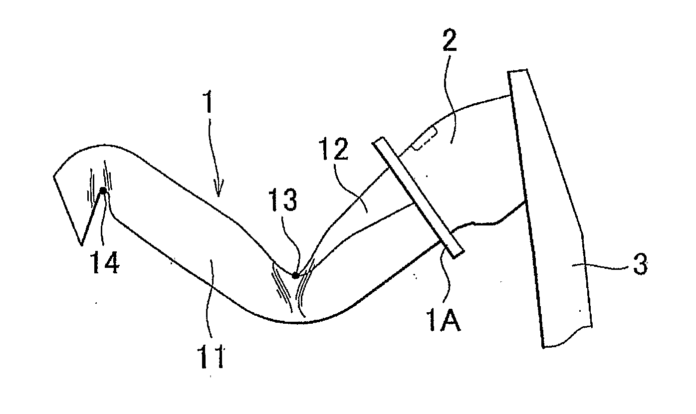
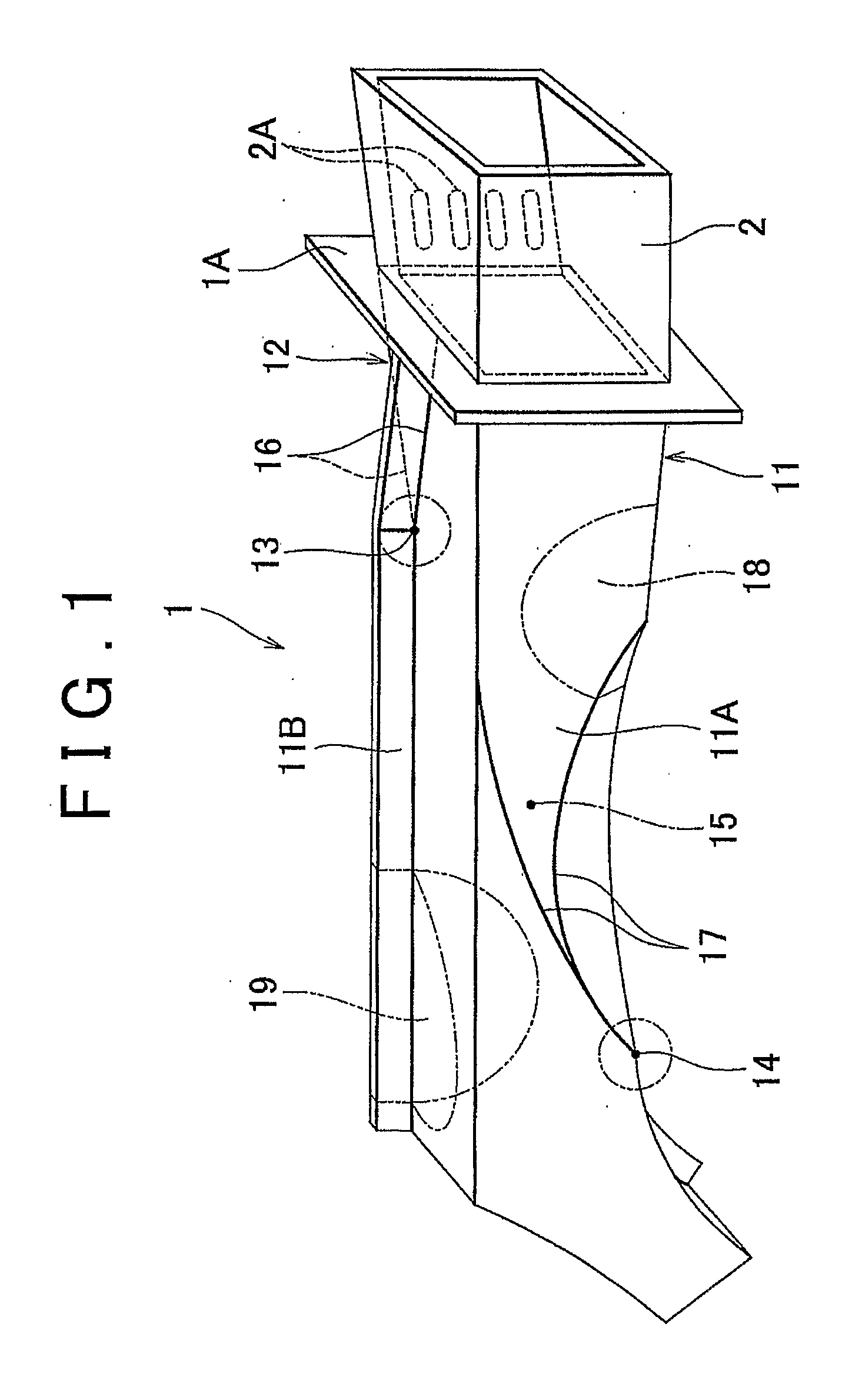
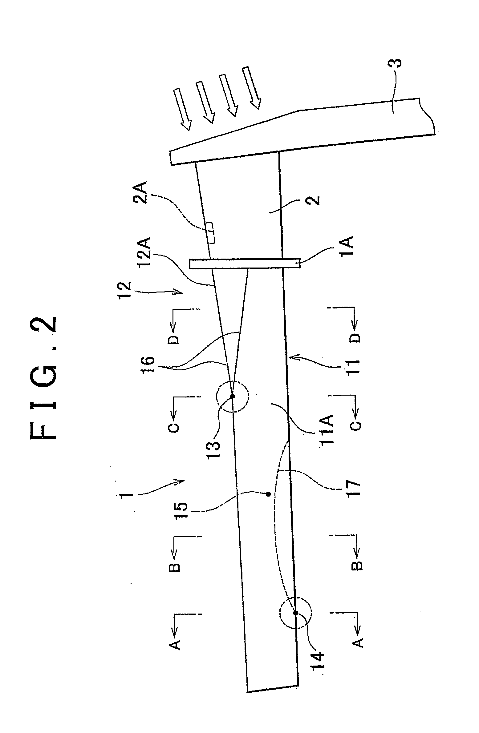
[0033]FIG. 1 is a perspective view of a front side member in a vehicle front structure according to the embodiment of the invention. FIG. 2 is a lateral view of FIG. 1. FIG. 3A is a cross-sectional view taken along a line A-A of FIG. 2. FIG. 3B is a cross-sectional view taken along a line B-B of FIG. 2. FIG. 3C is a cross-sectional view taken along a line C-C of FIG. 2. FIG. 3D is a cross-sectional view taken along a line D-D of FIG. 2. Further, FIG. 4 is a perspective view of a portion of the vehicle front structure according to the embodiment of t...


PUM


Abstract

A front buckling point and a rear buckling point are set at non-end positions along a longitudinal direction of a front side member respectively. Further, the front buckling point and the rear buckling point are respectively arranged at different positions in the width and vertical directions of the front side member. The front buckling point is arranged on an outboard and upper side of the front side member. The rear buckling point is arranged on an inboard and lower side of the front side member.

Description

BACKGROUND OF THE INVENTION[0001]1. Field of the Invention[0002]The invention relates to a vehicle front structure, and more particularly, to a vehicle front structure having a framework member that is appropriately deformed when a load is input to the vehicle front structure in a longitudinal direction of a vehicle.[0003]2. Description of the Related Art[0004]A vehicle front structure is required to absorb a load received upon a collision of a vehicle or the like. As a structure for suitably absorbing such a load, there is described in Japanese Patent Application Publication No. 2008-207619 (JP-A-2008-207619) a vehicle framework structure having a plurality of buckling lines, the lower portions of which are inclined forward, arranged side by side on a longitudinally extending portion of a front side member that forms a framework of a vehicle.[0005]In the described vehicle framework structure, because the buckling lines are formed, the front side member may be collapse along the buc...

Claims


Application Information

Patent Timeline
IPC IPC(8): B62D25/08
CPCB62D21/152
Inventor MORI, TAKEO
Owner TOYOTA JIDOSHA KK
Why Eureka
Try Eureka