Height sensor for an air spring

Active Publication Date: 2014-05-29
INFINITY ENGINEERED PROD LLC
View PDF1 Cites 3 Cited by
  • Summary
  • Abstract
  • Description
  • Claims
  • Application Information

AI Technical Summary

Benefits of technology

The technical problem of this patent is to create an air spring height sensor that can reliably transmit height signals from one part of the system to another.

Problems solved by technology

It may be seen as an objective technical problem to provide an air spring height sensor which enables a more reliable transmission of a height signal from a first measuring element in form of a height measuring signal transmitter to a second measuring element in form of a receiver.

Method used


Image

  • Height sensor for an air spring
  • Height sensor for an air spring
  • Height sensor for an air spring

Examples


Embodiment Construction

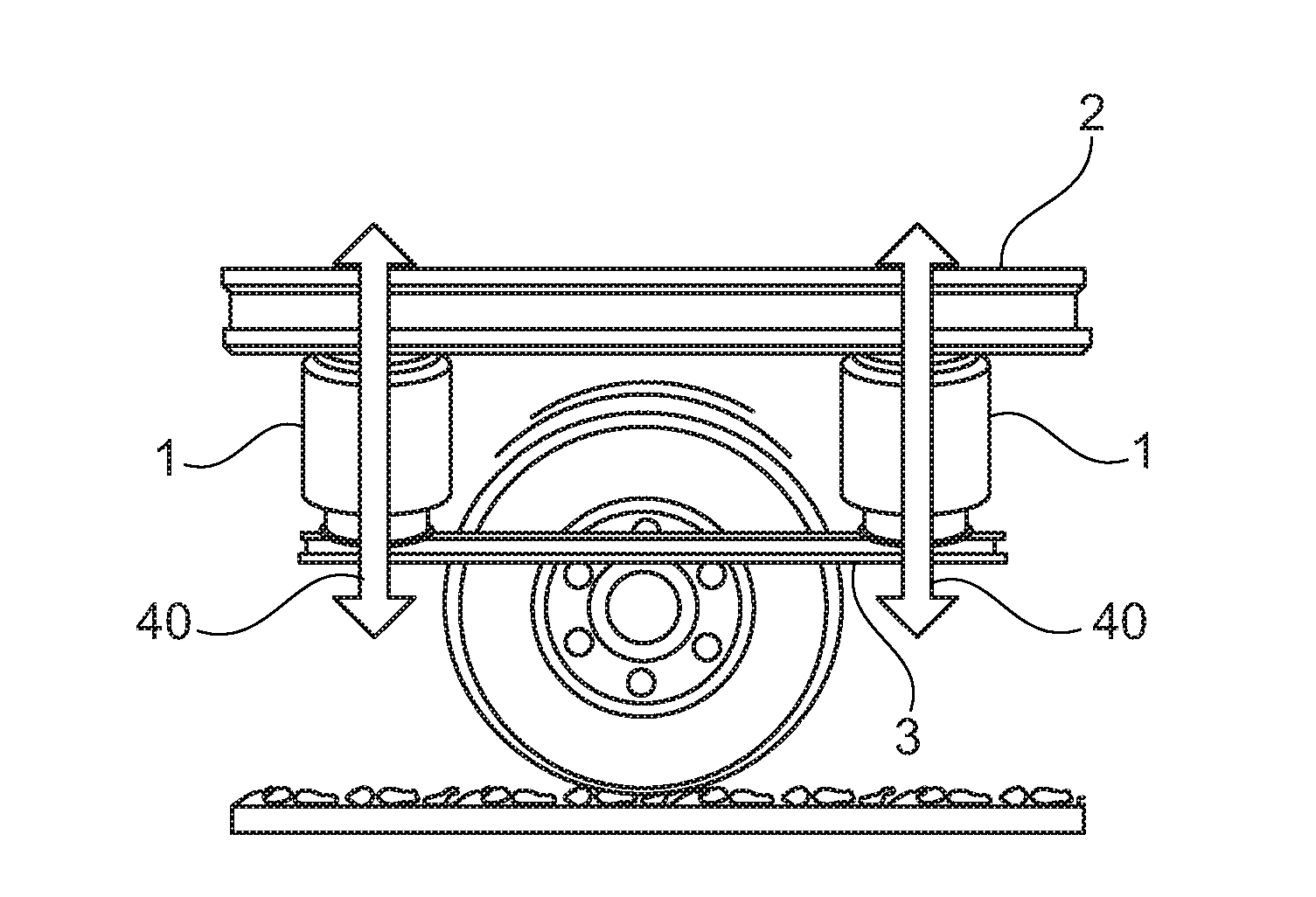
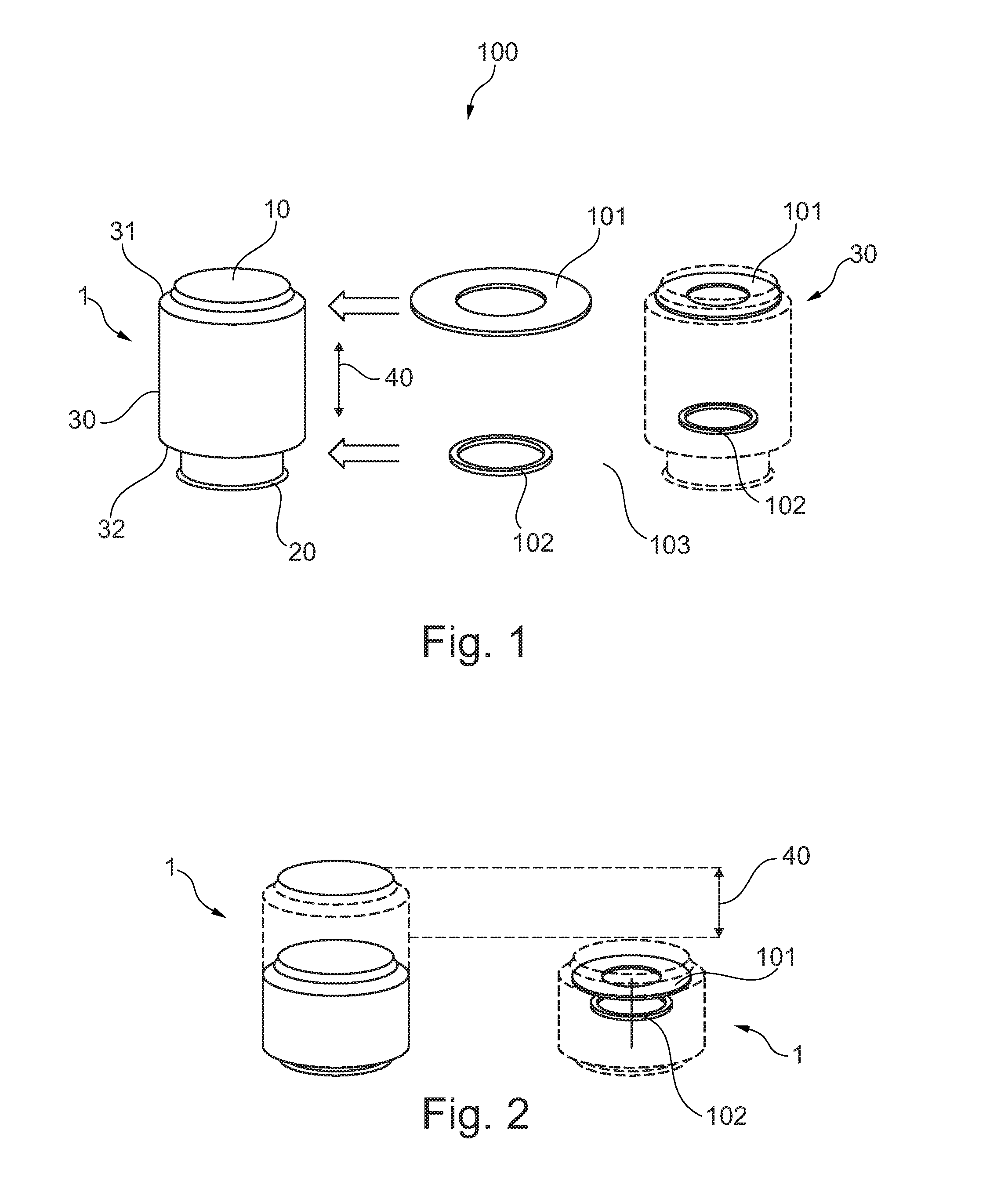
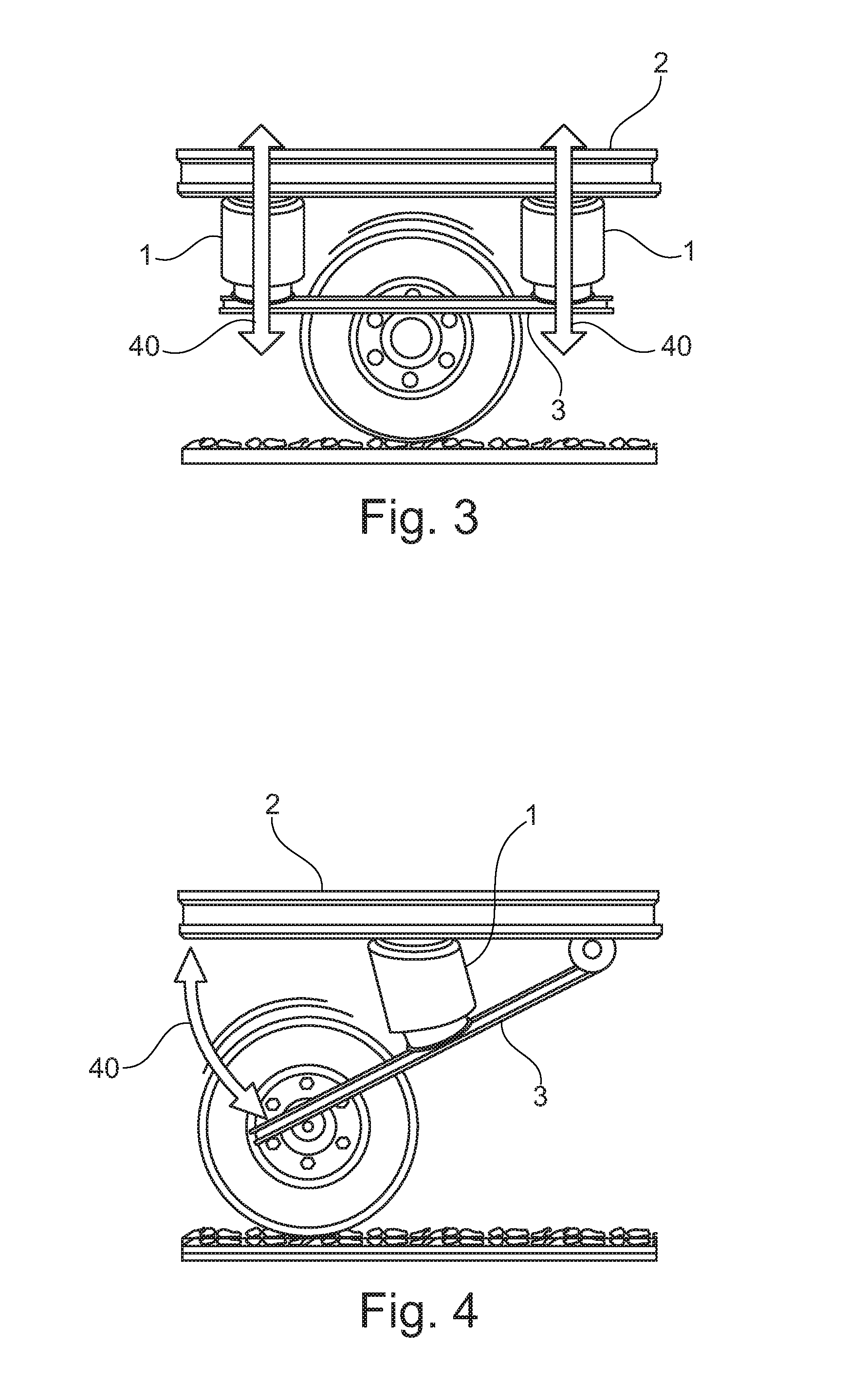
[0077]FIG. 1 illustrates an air spring 1 with a first mounting element 10 and a second mounting element 20. The air spring further comprises a belly 30 with a first edge 31 and a second edge 32. The first edge 31 of the belly 30 is mechanically interconnected with the first mounting element 10 and the second edge 32 is mechanically interconnected with the second mounting element 20.

[0078]The belly encloses an air volume such that the working stroke 40 of the air spring represents a movement of one of the first mounting element 10 and the second mounting element 20 towards the other one of the first mounting element 10 and the second mounting element 20.

[0079]An air spring height sensor 100 with a receiver 101 in form of a coil and a height measuring signal transmitter 102 is located within the air volume of the air spring as indicated by the air spring illustrated in dotted lines. The receiver 101 is located close to the first mounting element 10 of the air spring and the height mea...


PUM


Abstract

The subject invention relates to an air spring height sensor. The air spring height sensor of this invention comprises a height measuring signal transmitter (102) and a receiver (101). The height measuring signal transmitter is adapted for transmitting a height signal. The receiver is adapted for sensing the height signal transmitted by the height measuring signal transmitter. The height signal indicates a distance between the height measuring signal transmitter and the receiver.

Description

[0001]This application claims benefit of European Patent Application Serial No. EP 12194294.0, filed on Nov. 26, 2012. The teachings of European Patent Application EP 12194294.0 are incorporated herein by reference in their entirety.FIELD OF THE INVENTION[0002]The invention relates to distance measurement and in particular to a distance sensor, an air spring height sensor and an air spring for a vehicle having an air spring height sensor or a distance sensor.BACKGROUND OF THE INVENTION[0003]Height or distance measurement has a wide variety of possible applications. However, the environment where the height measurement is being made can present a wide variety of challenges. This is particularly the case in situations where height or distance measurements are being made in automotive applications. For example, in measuring the height of a vehicle frame above the surface of a road, challenges are typically presented by road noise, dirt, dust, and vibrations which are normally present i...

Claims


Application Information

Patent Timeline
IPC IPC(8): G01M17/04G01S15/08B60G11/26
CPCG01M17/04G01S15/08B60G11/26F16F9/3292F16F9/05
Inventor MAY, LUTZ
Owner INFINITY ENGINEERED PROD LLC
Why Eureka
Try Eureka