Drill thread milling cutter

a drill thread and cutter technology, applied in the direction of gear cutting tools, milling equipment, multi-purpose tools, etc., can solve the problems of affecting the damage or destruction of the said thread milling region, and the relatively long service life of the drill thread milling cutter. , to achieve the effect of improving the chip breaking behavior, improving the service life of the tool, and being economical

Inactive Publication Date: 2006-09-28
EMUGE WERK RICHARD GLIMPEL & FAB FUR PRAZISIONSWERKZEUGE
View PDF13 Cites 23 Cited by
  • Summary
  • Abstract
  • Description
  • Claims
  • Application Information

AI Technical Summary

Benefits of technology

[0012] The drill thread milling cutter is rotatable about an axis at least in one direction of rotation (cutting direction) and has firstly a drilling region with at least one drilling cutting edge for producing a bore in a workpiece and secondly a thread milling region with at least one milling cutting edge for the subsequent milling of a thread in the bore of the workpiece. According to the invention, more than twice as many milling cutting edges as drilling cutting edges are provided in the direction of rotation or at the circumference of the tool. As a result, a higher milling cutting capacity can be achieved than in the prior art, especially since the stock-removal capacity during the thread milling is in principle lower than during the drilling.
[0029] The proposals mentioned lead in each case to an improved drill thread milling tool, with which the cutting of long-chipping material such as steel is possible for the first time. In particular, a drill thread milling cutter is provided which is characterized by improved chip breaking behavior, so that both short- and long-chipping materials can be readily worked. The service life of the tool is thus relatively long, so that the cutter can be used economically.

Problems solved by technology

Whereas drill thread milling cutters of the previously known type can usually readily work short-chipping material, such as grey cast iron and brass for example, problems arise if long-chipping material, such as steel for example, is to be machined.
This is because the long chips get into the thread milling region of the tool during the drilling, so that said thread milling regions may be damaged or destroyed.
Furthermore, it has been found in tests carried out by the applicant that the previously known drill thread milling cutters of the type mentioned at the beginning are relatively susceptible to fracture, in particular when long-chipping and / or high-strength material such as steel is machined.
In addition, the known drill thread milling cutters, as long as they are ready for operation, have a relatively low cutting capacity.

Method used


Image

  • Drill thread milling cutter
  • Drill thread milling cutter
  • Drill thread milling cutter

Examples


Embodiment Construction

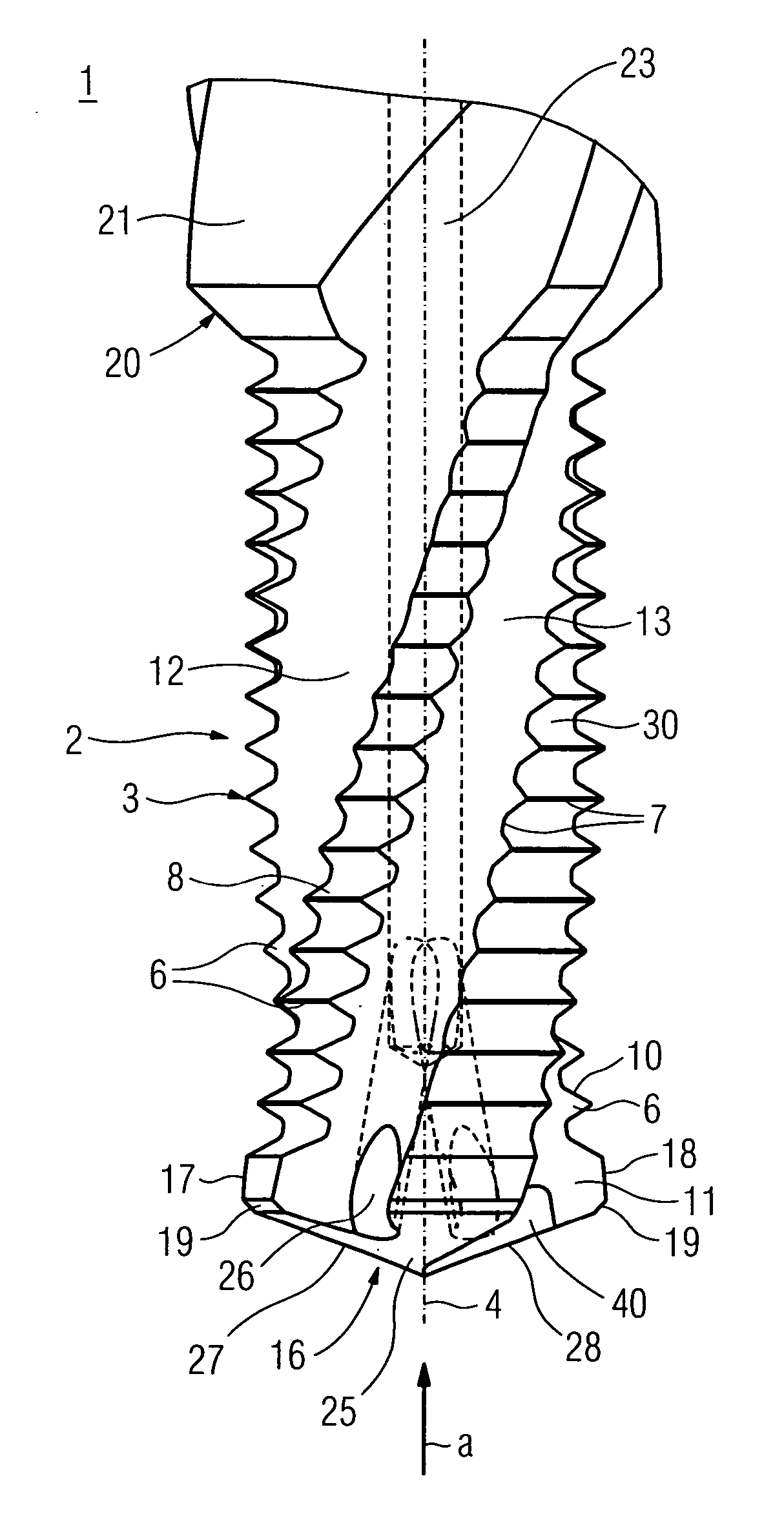
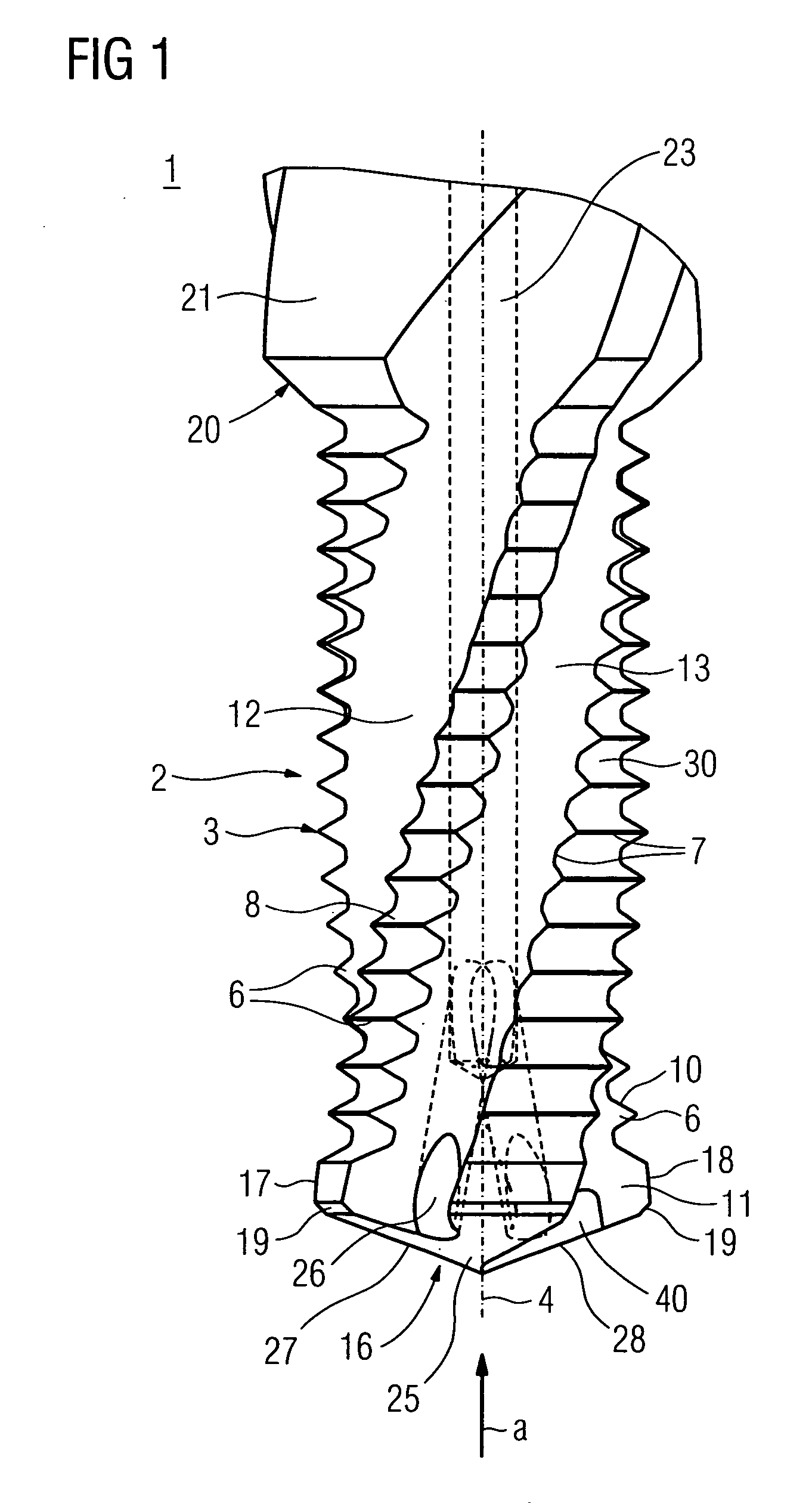
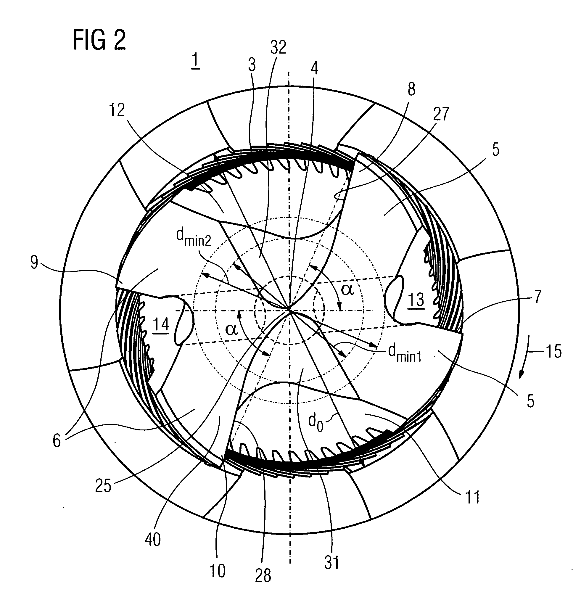
[0035] Sketched in FIGS. 1 to 3 is a drill thread milling cutter 1 which has an, in particular cylindrical, shank 21 for the tool mounting in a machine tool. A working region (cutting part) 2 reduced in diameter is formed on the other end of the shank 21, in particular in one piece or by attaching at least one prefabricated part. When it is in use, the tool or drill thread milling cutter 1 rotates about its axis 4, which passes through the shank 21 and the working region 2 and is generally a longitudinal axis and / or main axis of inertia, in the direction of rotation 15, in the present case clockwise or right-hand rotation (right-hand cutting).

[0036] The working region 2, at its end, has a drilling region 40 for producing a bore (a hole or a recess) in a workpiece and, at an essentially cylindrical circumference (or: envelope end) 3, has a thread milling region 30, arranged axially offset from the drilling region 40 with respect to the axis 4, for producing a thread in the bore, pro...


PUM

PropertyMeasurementUnit
distanceaaaaaaaaaa
distanceaaaaaaaaaa
rake angleaaaaaaaaaa

Abstract

The invention relates to a drill thread milling cutter (1) for producing a bore and for the subsequent milling of a thread in the bore, said drill thread milling cutter (1) having a working region (2), on the circumference (3) of which a number of drilling and milling cutting edges are arranged. A number of milling cutting edges (7, 8, 9, 10) greater than the number of drilling cutting edges (17) by a factor greater than 2 are arranged or are effective in the direction of rotation.

Description

RELATED APPLICATION [0001] The present application claims priority to German Application Serial No. 10 2005 014 422.5, filed Mar. 24, 2005, and entitled “Drill Thread Milling Cutter.”TECHNICAL FIELD [0002] The invention relates to a drill thread milling cutter. BACKGROUND OF THE INVENTION [0003] Drill thread milling cutters of this type are known, for example, from WO 2004 / 022274 A1 or U.S. Pat. No. 4,651,374 A or U.S. Pat. No. 4,761,844 A or from Handbuch der Gewindetechnik und Frastechnik [Manual of threading practice and milling practice], publisher: EMUGE-FRANKEN, publishing firm: Publicis Corporate Publishing, year of publication: 2004 (ISBN 3-89578-232-7), page 354. With such a tool, it is possible first of all to make a generally cylindrical bore in a workpiece. For this purpose, known drill thread milling cutters have drilling cutting edges with which the bore can be produced. Once this has been done, the cutter is fed in radially, i.e. it is displaced from the centre of the...

Claims


Application Information

Patent Timeline
Patent Type & Authority Applications(United States)
IPC IPC(8): B23C3/00
CPCB23G5/188B23G2200/04B23G2200/143B23G2200/148B23G2200/26Y10T409/30056B23G2240/12Y10T407/1745Y10T407/172Y10T409/300504Y10T408/9048B23G2200/30
Inventor GLIMPEL, HELMUTSPERBER, MATTHIAS
Owner EMUGE WERK RICHARD GLIMPEL & FAB FUR PRAZISIONSWERKZEUGE
Why Eureka
Try Eureka