Downhole motor seal and method

US20060216178A1Inactive Publication Date: 2006-09-28SCHLUMBERGER TECH CORP

Image

  • Downhole motor seal and method
  • Downhole motor seal and method
  • Downhole motor seal and method

Examples


Embodiment Construction

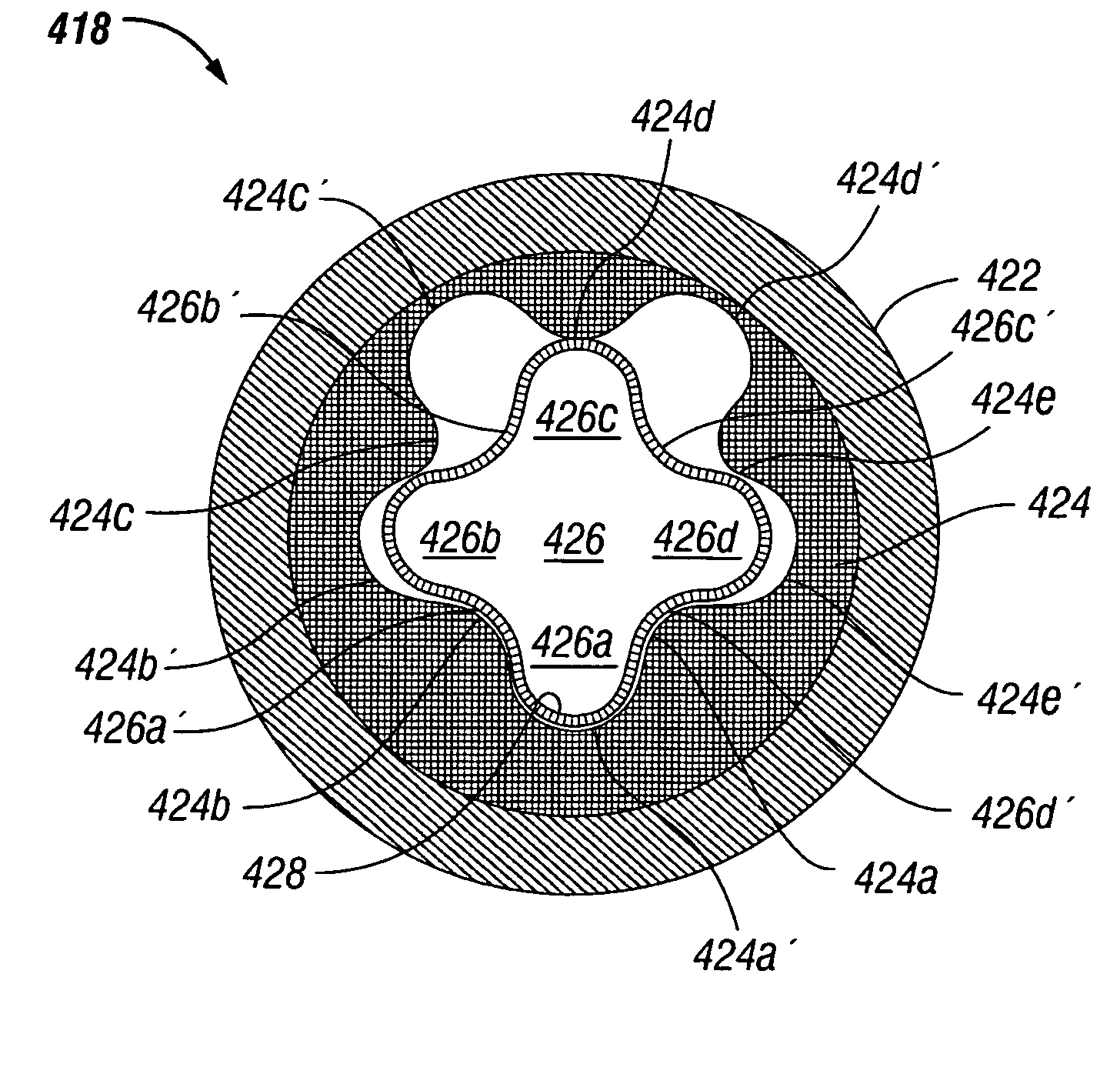
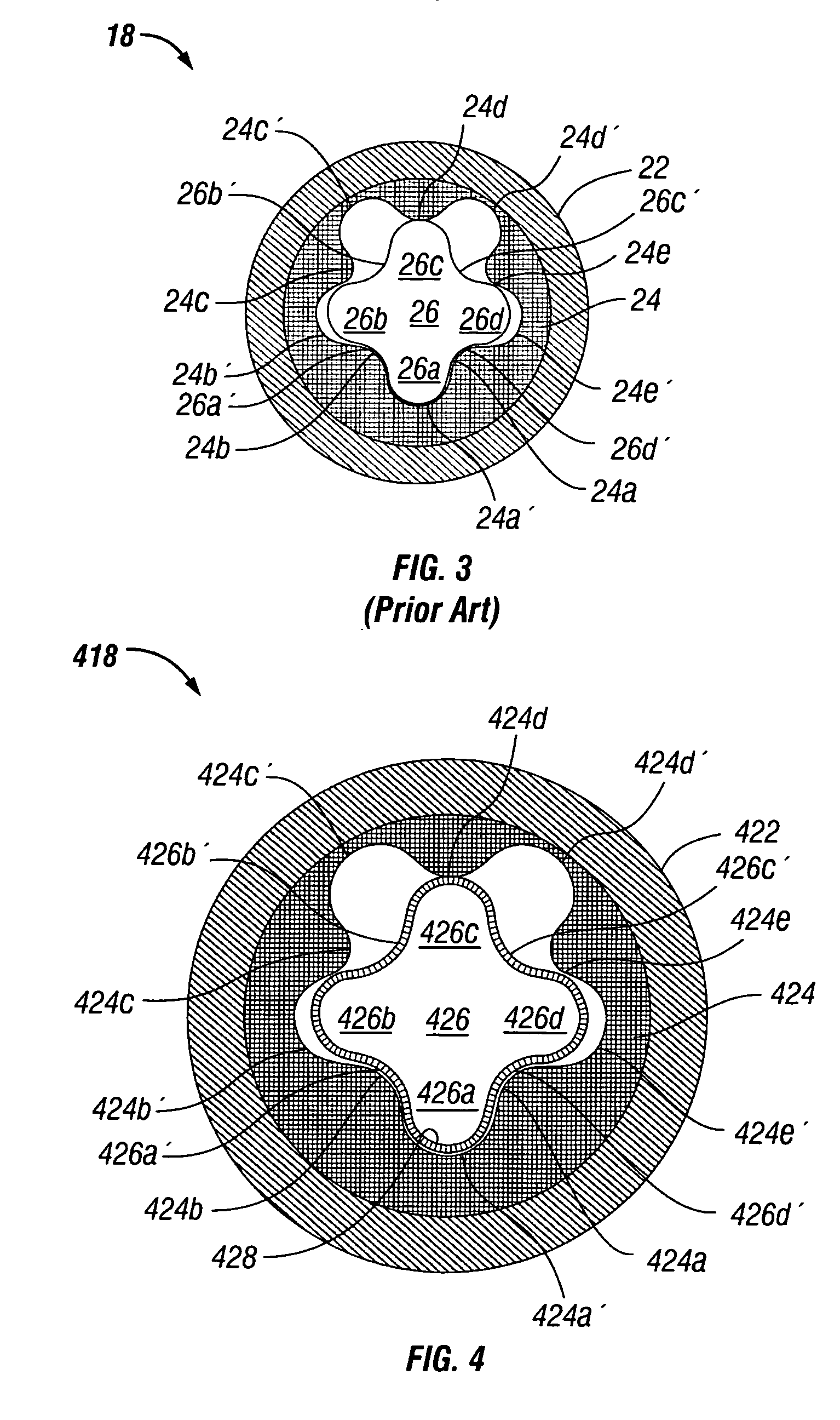
[0032]FIG. 4 shows a cross-sectional view of the power section 418 of a downhole motor according to the present invention. The power section 418 generally includes a tubular housing 422 which houses a motor stator 424 within which a motor rotor 426 is rotationally mounted. The power section 418 converts hydraulic energy into rotational energy by reverse application of the Moineau pump principle, as is well known.

[0033] The stator 424 has five helical lobes, 424a-424e, which define five helical cavities, 424a′-424e′. The stator may be constructed substantially of a chrome-plated stainless steel, similar to the makeup of conventional rotors, but the present invention does not preclude the stator from incorporating an elastomeric inner portion in the traditional manner. Thus, the stator may forego—or alternatively employ—elastomeric material for its inner profile. In the former case, the sealing utility of the motor's progressing cavities would be ensured by an elastomeric sleeve on t...


PUM

PropertyMeasurementUnit
Pressureaaaaaaaaaa
Diameteraaaaaaaaaa
Surface roughnessaaaaaaaaaa

Abstract

The rotor of a downhole motor includes a mandrel having at least one radial lobe, and an elastomeric tubular sleeve compressed about the mandrel so as to establish frictional engagement therebetween. The sleeve is compressed about the mandrel through one of various processes, including heat shrinking, vacuum shrinking, and stretching.

Description

BACKGROUND OF THE INVENTION [0001] 1. Field of the Invention [0002] The present invention relates to mud-driven motors used in the drilling of wellbores for hydrocarbon production. More particularly, the invention relates to the sealing elements employed within the power section of a downhole drilling motor. [0003] 2. Background of the Related Art [0004] The concept of downhole motors for driving an oil well drill bit is more than one hundred years old. Modem downhole motors, also known as progressive cavity motors or simply mud motors, are powered by circulating drilling fluid (mud), which also acts as a lubricant and coolant for the drill bit, through a drill string in which a downhole motor is conveyed. Prior art FIG. 1 shows a conventional downhole motor assembly. The motor assembly 10 generally includes a rotatable drill bit 12, a bearing / stabilizer section 14, a transmission section 16 which may include an adjustable bent housing, and a motor power section 18. The bent housing...

Claims


Application Information

Patent Timeline
28 Sep 2006
Publication
US20060216178A1
IPC
F01C5/00; F04C5/00; F16N13/20; F04C2/00; E21B4/02; F04C2/107
CPC
E21B4/02; F04C2/1075; Y10T29/49863; F04C2230/26; F04C2230/20
Inventors
SINDT, OLIVIER; DOWNTON, GEOFF