Receiving box

a technology for receiving boxes and boxes, applied in the field of receiving boxes, can solve the problems of low mechanical strength of ecu-centralized receiving boxes, complicated operation of connecting wire fittings and installation of wire harnesses, and increase the space for wire harnesses, so as to improve the efficiency of operation and high mechanical strength

Inactive Publication Date: 2006-09-28
YAZAKI CORP
View PDF2 Cites 19 Cited by
  • Summary
  • Abstract
  • Description
  • Claims
  • Application Information

AI Technical Summary

Benefits of technology

[0042] In the present invention, there can be provided the electric circuit board receiving box which can greatly enhance the efficiency of the operation for connecting the board connectors of the plurality of electric circuit boards (received in the receiving box in a stacked manner) to the mating connectors of the wire harnesses, and has the high mechanical strength.

Problems solved by technology

Therefore, connector fitting-operations and the installation of the wire harnesses have become complicated, and besides an installation space for the wire harnesses has increased.
Therefore, the ECU-centralized receiving box has a low mechanical strength.
Generally, in many cases, connectors, mounted on ECU boards received within an ECU-centralized receiving box, are located randomly even if the connectors belong to the same installation system, and each time the connectors are connected together, it is required to carry out a cumbersome connector-connecting operation in which the connectors to be connected together are first found, and then are connected together.
The number of the connectors increases with the increase of the number of ECU boards received within the ECU-centralized receiving box, and therefore the burden to find out the connectors to be connected together greatly increases.
Also, much time and labor are required for the connector-connecting operation, and besides the possibility of erroneous connections increases.
Furthermore, the wire harnesses, connected through the connectors, are installed in a complicated manner, and therefore a maintenance operation can not be easily effected, and besides the quality of the product is lowered.

Method used


Image

  • Receiving box
  • Receiving box
  • Receiving box

Examples


first embodiment

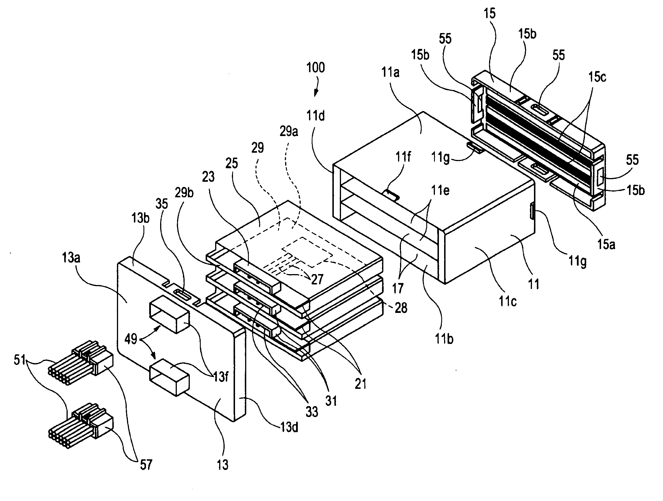
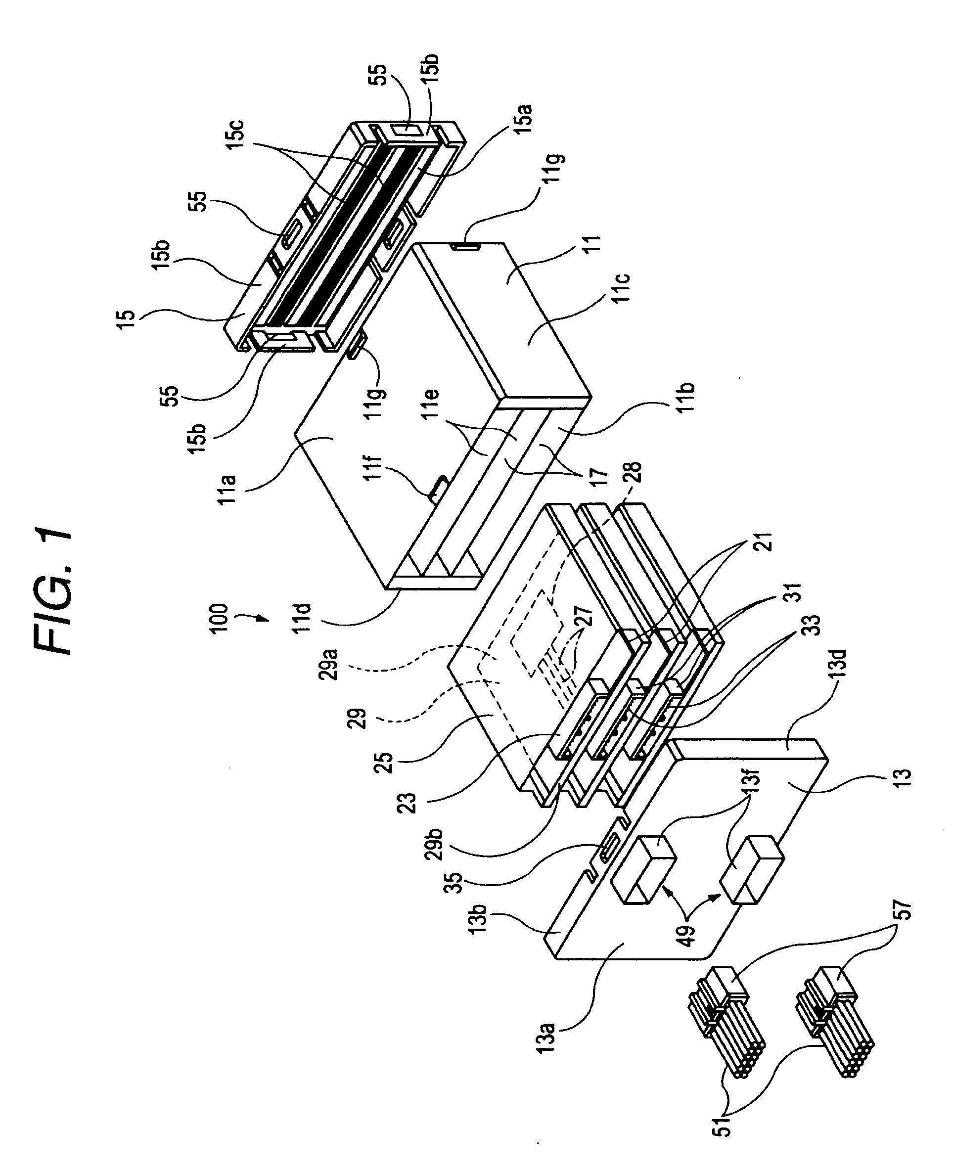
[0063]FIG. 1 is an exploded, perspective view of the first embodiment of an electric circuit board receiving box of the invention, FIG. 2 is an exploded, perspective view showing a connection circuit member and a lid member of FIG. 1, and FIG. 3 is a vertical cross-sectional view of the electric circuit board receiving box of FIG. 1 having electric circuit boards received therein.

[0064] As shown in FIGS. 1 to 3, the first embodiment of the electric circuit board receiving box 100 of the invention can receive the plurality of electric circuit boards 21 in a stacked manner, and each of the electric circuit boards 21 includes a base board 29 having electric circuit patterns 27 formed thereon, and a board connector 23 which is mounted on the base board 29 to extend along one end edge 29b of this base board 29, and is electrically connected to the electric circuit patterns 27. The electric circuit board receiving box 100 comprises:

[0065] a receiving box body 11 which has an opening for...

modified example

[0082] A modified example of the first embodiment of the electric circuit board receiving box of the invention will be described with reference to FIGS. 4 and 5. FIG. 4 is an exploded, perspective view of the modified electric circuit board receiving box, and FIG. 5 is an exploded, perspective view showing a connection circuit member and a lid member of FIG. 4. The modified electric circuit board receiving box differs from the electric circuit board receiving box of the first embodiment only in the connection circuit member, and the other portions are similar, and therefore those portions identical to those of the first embodiment will be designated by identical or corresponding reference numerals, respectively, and explanation thereof will be simplified or omitted.

[0083] As shown in FIGS. 4 and 5, the modified electric circuit board receiving box 150 (which is the modified example of the first embodiment) can receive a plurality of electric circuit boards 21 in a stacked manner, a...

second embodiment

[0095] Next, a second embodiment of an electric circuit board receiving box of the invention will be described with reference to FIG. 6. FIG. 6 is a vertical cross-sectional view of the second embodiment of the electric circuit board receiving box of the invention.

[0096] As shown in FIG. 6, the electric circuit board receiving box 200 of the second embodiment is similar to the electric circuit board receiving box 100 of the first embodiment except that there is not provided a rear lid and that a receiving box body 121 is partially different from that of the first embodiment. Therefore, those portions identical to those of the first embodiment will be designated by identical or corresponding reference numerals, respectively, and explanation thereof will be simplified or omitted.

[0097] Elastic piece portions 125 are formed respectively at rear end portions of right and left side walls 11c and 11d of each of board receiving chambers 17 formed in the receiving box body 121. A pair of ...


PUM


Abstract

A receiving box for receiving a plurality of electric circuit boards having board connectors respectively, includes a receiving box body that is configured to receive the electric circuit boards therein, and has an opening for exposing the board connectors therethrough, a lid member that has a connector for connecting to a mating connector of a wire harness, and a connection circuit member that has a plurality of connectors for electrically connecting to the board connectors of the electric circuit boards, and is mounted on the lid member so as to electrically connect the connector of the lid member to the connectors of the connection circuit member. When the lid member is attached to the receiving box body to cover the opening in the receiving box body, the connectors of the connection circuit member are collectively fitted to the board connectors respectively.

Description

BACKGROUND OF THE INVENTION [0001] This invention relates to a receiving box for receiving a plurality of electric circuit boards in a stacked manner. [0002] Many on-vehicle electrical equipments and electronic control units (hereinafter often referred to as “ECU”) for controlling these electrical equipments are mounted in a dispersed manner on various portions of a vehicle such as an automobile. Generally, each ECU is mounted on an ECU board (or electronic control board), and these ECU boards are received within separate receiving boxes, respectively, and these receiving boxes are mounted in a dispersed manner on the various portions of the vehicle. [0003] In recent years, with a high value-added design of vehicles such as automobiles, there is a tendency for the number of ECUs to increase, and therefore an installation space for the ECUs has increased, and also the number of wire harnesses (connecting electrical equipments to the ECUs), as well as the number of connectors used for...

Claims


Application Information

Patent Timeline
Patent Type & Authority Applications(United States)
IPC IPC(8): H05K1/00
CPCB60R16/0238G11B33/12H05K5/0021H05K5/0065H05K7/1422
Inventor YAMANASHI, MAKOTOISHII, KEIICHITAGUCHI, NAOTO
Owner YAZAKI CORP
Why Eureka
Try Eureka