Device for placing a looped belt under tension

a technology of looped belts and devices, applied in the direction of fastening means, gearing, washing machines, etc., can solve the problems of machine downtime, machine failure, and belts that are under proper tension when installed, so as to improve flexibility in designing a machine, the effect of easing constraints

Active Publication Date: 2006-09-28
YORK IND
View PDF34 Cites 33 Cited by
  • Summary
  • Abstract
  • Description
  • Claims
  • Application Information

AI Technical Summary

Benefits of technology

[0011] An object of the invention is to remedy the problems of the prior art noted above. In particular, an object of the invention is to provide a device for placing a looped belt under tension, the device being designed so that it is inexpensive and can be employed in multiple instances to apply proper tension to all of the belts of a complex machine such as a photocopier or medical apparatus. A further object of the invention is to provide a single device that is versatile enough to enable either a static or a dynamic mounting for a belt and that can be mounted at virtually any location on a machine, thereby easing constraints and improving flexibility in designing a machine.

Problems solved by technology

If a belt is too loose it slips on the pulleys and does not turn them reliably, so that the apparatus malfunctions.
Belts tend to stretch during use, so that a belt that is under proper tension when installed may later be too loose; and during operation of a machine, vibrations are often set up that change the tension on a belt many times a second.
But this entails machine downtime and is expensive in terms of labor and lost output.
This type of mount is likely to be costlier than a static mount.
While pulley mounts are not individually expensive, their total cost in a complex machine is not inconsiderable.
This entails the cost of design and engineering to determine the best mount design at each location in a machine, the cost of manufacturing to the several design specifications, and the cost of familiarizing service personnel with the several designs.
All of the problems described above are compounded by the many different designs of machines that have belt drives.
These costs contribute considerably to the total cost of the machines.

Method used


Image

  • Device for placing a looped belt under tension
  • Device for placing a looped belt under tension
  • Device for placing a looped belt under tension

Examples


Embodiment Construction

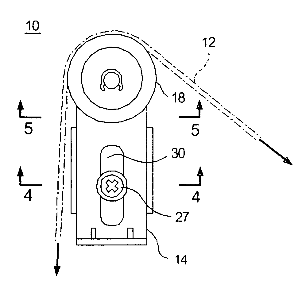
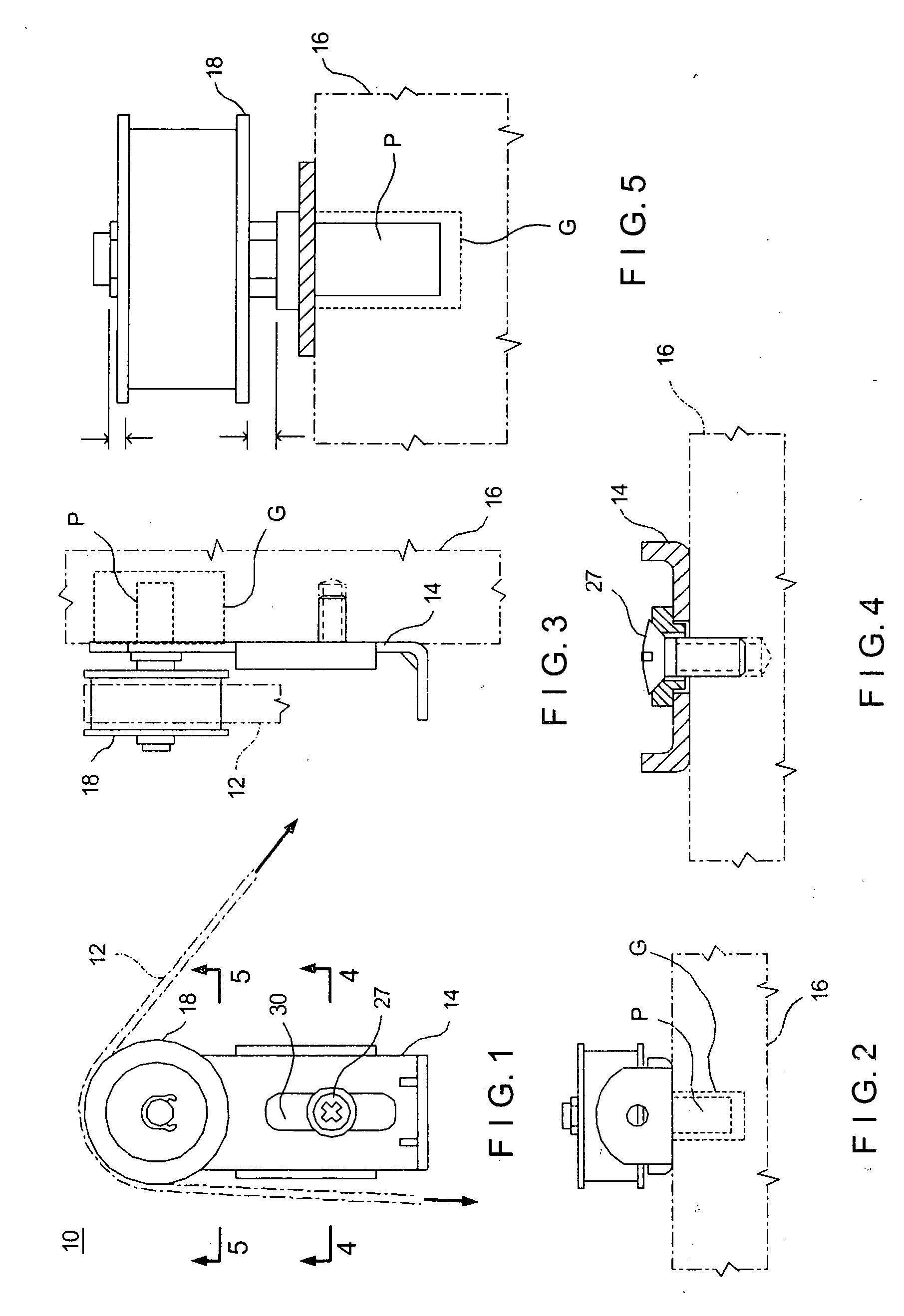
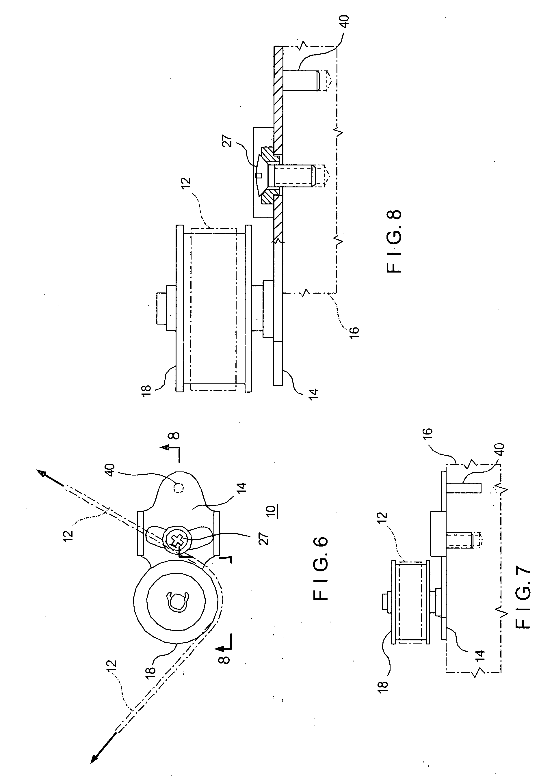
[0040]FIGS. 1, 3, 6-9, 11, 20-23, 25, 26, 28, 29, 31 and 32 are views, in same cases fragmentary, of several embodiments of a device 10 and a looped belt 12 that the device 10 places under tension. The belt 12 and the pulley 18 are illustrated as smooth, but a belt and pulley with teeth can be used, as those skilled in the art will understand. The other figures omit the belt 12 but show various features of the several embodiments. The device 10 comprises a tension arm 14 for mounting on a base 16, either directly, as in FIG. 4, or indirectly via a spring bracket, as described below. A pulley 18 is mounted on the tension arm 14 for engaging the belt 12. A mounting bushing 20a or 20b (FIG. 12A and FIG. 12B, respectively; see also FIGS. 18A and 18B; 24A and 24B; and 27A and 27B) provides for a dynamic mode of operation (FIGS. 12A, 18A, 24A and 27A) or a static mode of operation (FIGS. 12B, 18B, 24B and 27B), as explained below.

[0041] The belt 12 forms a loop, and biasing means such as...


PUM


Abstract

A tensioning device has a tension arm mounted on a base. A pulley is mounted on the tension arm for engaging a looped belt. By changing mounting bushings, one can select either a static mode wherein the tension arm is held stationary relative to the base, or a dynamic mode wherein, in response to a changing force applied between the pulley and the belt (due to vibrations or load changes, for example), the tension arm moves relative to the base in such a manner as to maintain the force substantially constant. Several such devices can be employed in a system for controlling the tension of a looped belt, one or more of the devices being in the static mode and one or more being in the dynamic mode. Several such systems can be employed in a complex machine such as a photocopier or medical apparatus for controlling the tension in a number of different belts.

Description

BACKGROUND OF THE INVENTION [0001] 1. Field of the Invention [0002] This invention relates to devices for placing a looped belt under tension and more particularly to such a device that is inexpensive and can be employed in multiple instances to apply proper tension to all of the belts of a complex machine such as a photocopier or medical apparatus. The invention relates also to a method of driving a looped belt in a mode of tensioning that is selectively static or dynamic. [0003] 2. Description of the Prior Art [0004] Many complex machines such as photocopiers and sophisticated medical apparatus employ one or more belt drives for turning pulleys and the axles on which they are mounted. The circular movements of the pulleys and axles are converted as may be required into rectilinear and other types of movement, which may be continuous or intermittent. [0005] The belts must all be placed under proper tension in order to work properly. If a belt is too tight it tends to cock pulleys a...

Claims


Application Information

Patent Timeline
Patent Type & Authority Applications(United States)
IPC IPC(8): F16H7/12
CPCF16H7/1263F16H7/1281F16H2007/0804F16H2007/0806F16H2007/0861F16H2007/0874F16H2007/088
Inventor SCHMID, HARTMUTO'DONNELL, PAUL
Owner YORK IND
Why Eureka
Try Eureka