
Vehicle seats

a seat and vehicle technology, applied in the field of seats for vehicles, can solve the problem that the massage unit does not provide discomfort to the passenger, and achieve the effect of convenient deformation or compression, effective massage, and easy connection

Active Publication Date: 2006-09-28
MATSUSHITA ELECTRIC WORKS LTD +1
View PDF9 Cites 74 Cited by
  • Summary
  • Abstract
  • Description
  • Claims
  • Application Information

AI Technical Summary

Benefits of technology

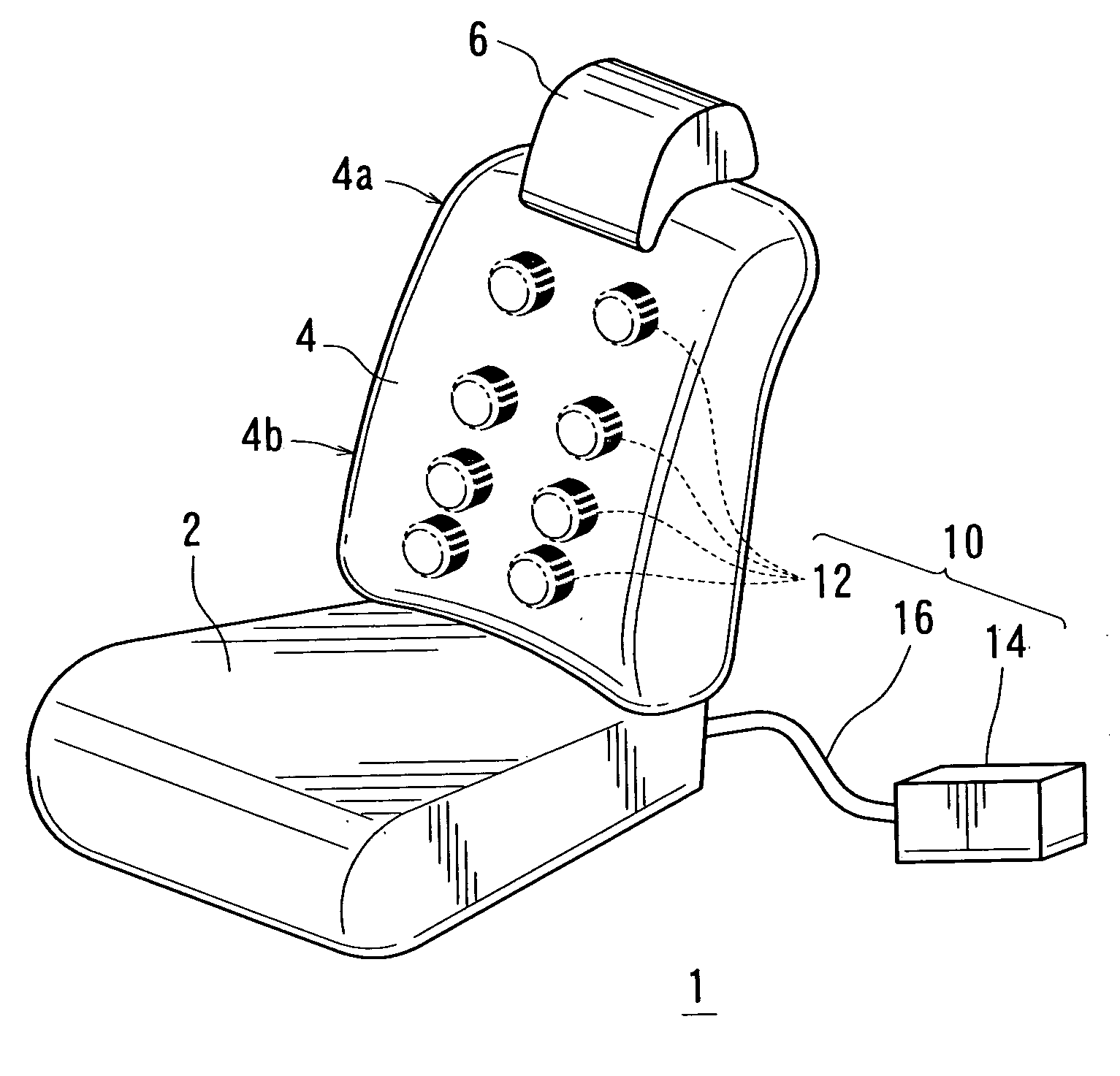
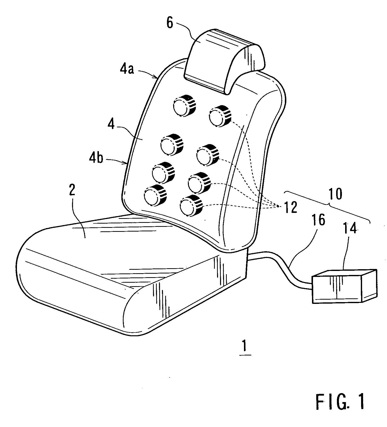
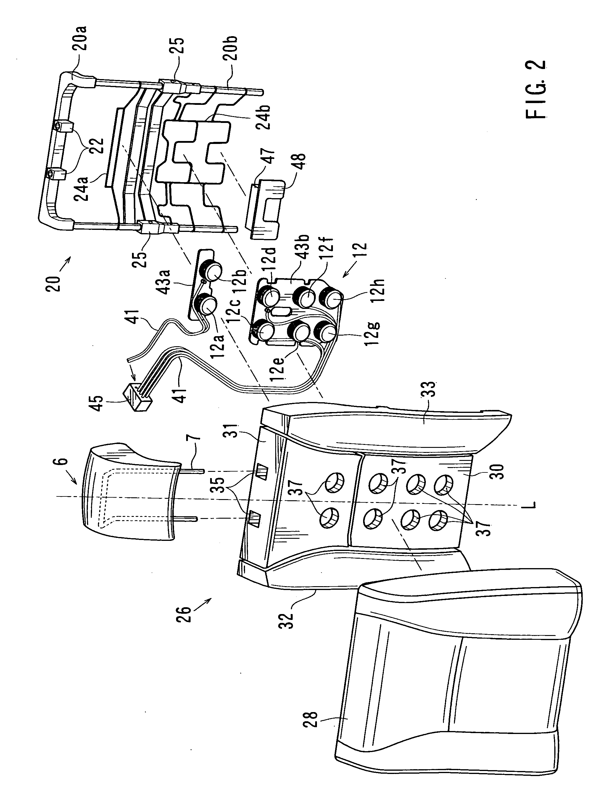
The present invention provides an improved power seat for vehicles that includes a massaging mechanism. The seat has a cushion pad with bores and massaging elements that can be compressed and expanded along the bores' movement axes. The massaging elements are connected to the cushion pad so they can easily deform or compress when not in use, providing comfort to the passenger. Special connector units are used to connect the air pipes and massaging elements, making it easy to connect the air pipes without adding extra space. The massaging elements can be directed to different directions to effectively massage the passenger's back side.

Problems solved by technology

Therefore, the massaging unit does not provide discomfort to a passenger when the passenger is sitting on the seat.

Method used


Image

  • Vehicle seats
  • Vehicle seats
  • Vehicle seats

Examples


Embodiment Construction

[0028] A representative example of the present invention has been described in detail with reference to the attached drawings. This detailed description is merely intended to teach a person of skill in the art further details for practicing preferred aspects of the present teachings and is not intended to limit the scope of the invention. Only the claims define the scope of the claimed invention. Therefore, combinations of features and steps disclosed in the foregoing detailed description may not be necessary to practice the invention in the broadest sense, and are instead taught merely to particularly describe detailed representative examples of the invention. Moreover, the various features taught in this specification may be combined in ways that are not specifically enumerated in order to obtain additional useful embodiments of the present teachings.

[0029] A detailed representative embodiment of the present teachings is shown in FIG. 1 to FIG. 9.

[0030] As shown in FIG. 1, a veh...


PUM


Abstract

A vehicle seat may include a seat back that has a back frame, a cushion pad attached to the back frame, and a massaging unit having a plurality of massaging elements. The cushion pad has a plurality of through bores that pass therethrough in the direction of thickness thereof. The massaging elements are constructed so as to be elastically deformed or compressed along moving axes and to be pneumatically expanded and contracted along the moving axes. The massaging elements are disposed in the through bores in a manner that the moving axes of the massaging elements extend along longitudinal axes of the through bores. The massaging elements have deformability or compressibility identical with or greater than the deformability or compressibility of the cushion pad when the massaging elements are not operated.

Description

BACKGROUND OF THE INVENTION [0001] 1. Field of the Invention [0002] The present invention relates to seats for a vehicle. More particularly, the present invention relates to seats of a vehicle that have a massaging function. [0003] 2. Description of the Related Art [0004] A seat of a vehicle having a massaging mechanism is already known. Such a seat (a power seat) is taught, for example, by Japanese Laid-Open Utility Model Publication No. 63-46136. [0005] In the known power seat, the massaging mechanism has a plurality of vibrating devices (hummers) that are provided to a cushion pad of a seat back. Typically, the vibrating devices are movably disposed within a plurality through holes formed in the cushion pad and are coupled to a drive unit having a drive motor. [0006] The vibrating devices thus disposed can be driven by the drive motor so as to discontinuously push the back of a passenger, thereby providing a massaging function for the passenger. As a result, the power seat thus c...

Claims


Application Information

Patent Timeline
Patent Type & Authority Applications(United States)
IPC IPC(8): A61H23/04
CPCA61H9/0078A61H2201/0134A61H2201/0149A61H2205/081B60N2/448B60N2/976B60N2/914
Inventor OZAKI, TAKASHIHATTORI, MASAKINISHIGUCHI, NOBORU
Owner MATSUSHITA ELECTRIC WORKS LTD
Learn More