Air suspension and electronically controlled suspension system

a suspension system and air suspension technology, applied in the field of air suspension, can solve the problems of deteriorating the motional performance of the vehicle, insignificant control benefits, and deteriorating ride comfort and travel stability, and achieve the effect of rapid and efficient stabilization of the movement of the vehicl

Inactive Publication Date: 2006-10-05
HL MANDO CORP
View PDF24 Cites 81 Cited by
  • Summary
  • Abstract
  • Description
  • Claims
  • Application Information

AI Technical Summary

Benefits of technology

[0013] Another object of the present invention is to provide an electronically controlled suspension system, wherein when a lateral motion occurs in a vehicle mounted with an air suspension, a spring rate of an air spring of the air suspension is controlled to rapidly and efficiently stabilize the movement of the vehicle.
[0014] A further object of the presen

Problems solved by technology

Such a roll phenomenon causes deterioration of ride comfort and travel stability.
However, in view of features of a pneumatic device, the conventional air suspension does not have a rapid response enough to respond to a lateral motion produced for a short period of time, resulting in insignificant control benefits.
Even in a case where the occurrence of the lateral motion is terminated and the vehicle should return to a normal travel condition, there is a problem in that it takes a great

Method used


Image

  • Air suspension and electronically controlled suspension system
  • Air suspension and electronically controlled suspension system
  • Air suspension and electronically controlled suspension system

Examples


Embodiment Construction

[0022] Hereinafter, preferred embodiments of the present invention will be described in detail with reference to the accompanying drawings. The objects, features and advantages of the present invention will be better understood through the embodiments. However, the present invention is not limited to the embodiments.

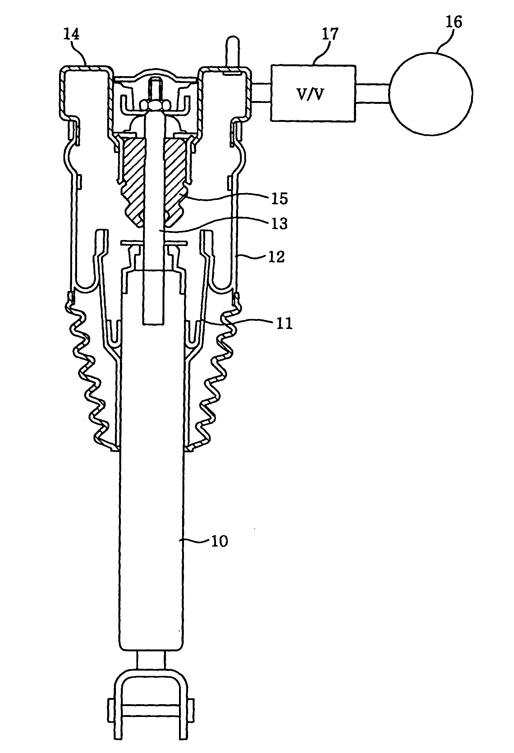
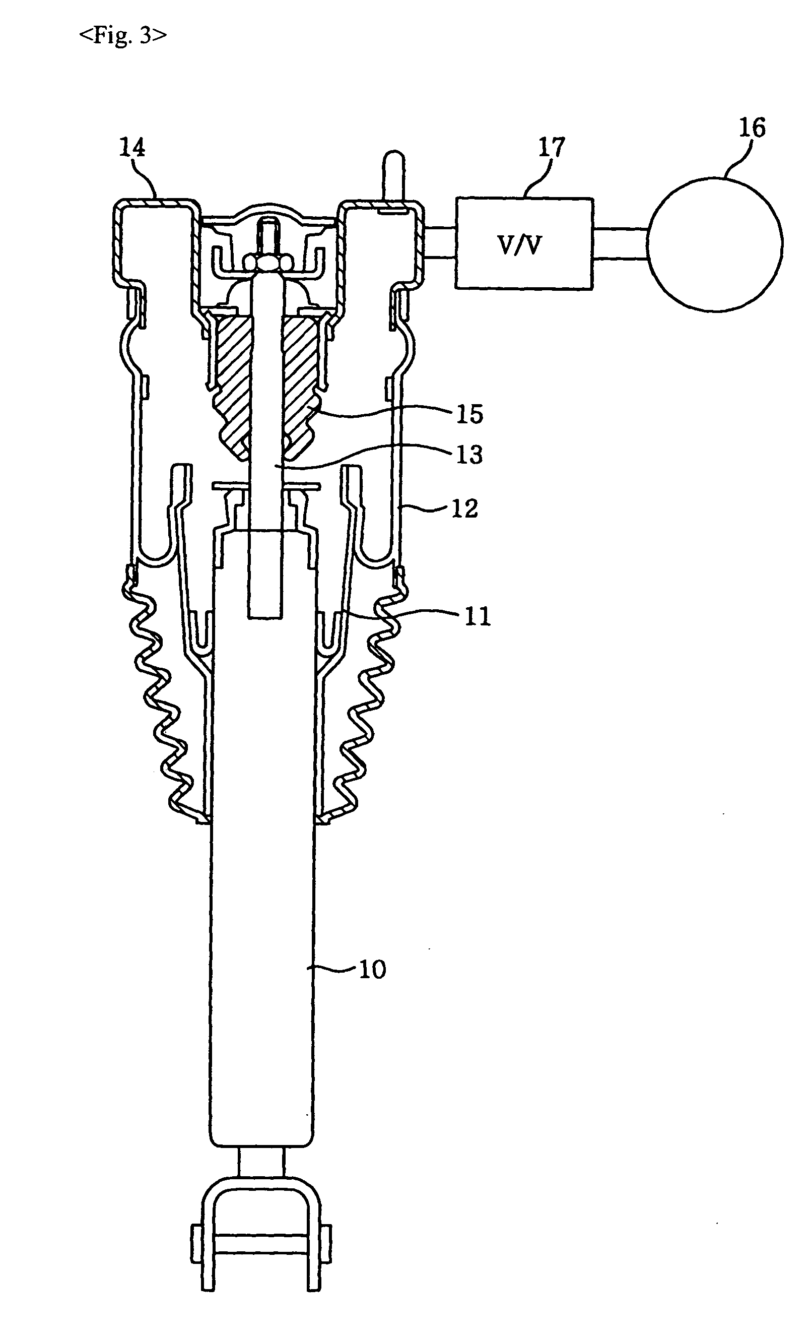
[0023]FIG. 3 is a sectional view showing the structure of an air spring employed in an air suspension according to the present invention. Referring to the structure, the air spring comprises a damper 10 as a vibration-proof and shock-absorbing device installed between a vehicle body and an axle of a vehicle to absorb a vibration or shock that the axle receives from a road when the vehicle travels; a cylindrical air piston 11 concentrically installed outside the damper 10; a rubber tube 12 airtightly coupled to an upper or lower end of the air piston 11 to function as an air spring; a cap 14 airtightly coupled to an upper portion of the rubber tube 12 and coupled to an u...


PUM


Abstract

The present invention relates to an air suspension and an electronically controlled suspension system. An electronically controlled suspension system of the present invention comprises an air suspension including a volume expander connected to a pressure acting volume of an air spring to expand the pressure acting volume, and a volume control valve for opening or closing the connection between the pressure acting volume and the volume expander; a mode-changing switch for applying a mode-setting key signal according to a driver's button operation; an electronic control unit for outputting a valve control signal for use in exhibiting a suspension characteristic of the vehicle in response to the mode-setting key signal from the mode-changing switch; and an air spring volume adjustor for controlling a spring rate of the air spring through adjustment of the pressure acting volume of the air spring by opening or closing the volume control valve in response to the valve control signal from the electronic control valve, thereby forcibly setting the suspension characteristic of the vehicle. The present invention is to control a spring rate of an air spring employed in an air suspension to a range of damping force characteristics of a relevant mode by selectively controlling a pressure acting volume of the air spring using a fast response valve in response to a signal corresponding to a driver's mode-changing operation. Thus, during sudden braking, rapid acceleration or cornering, a driver can conveniently change characteristics of a vehicle mounted with the air suspension by operating a button within the vehicle, resulting in maximization of consumers' satisfaction.

Description

BACKGROUND OF THE INVENTION [0001] 1. Field of the Invention [0002] The present invention relates to an air suspension, and more particularly, to an air suspension and an electronically controlled suspension (ECS) system, wherein when a lateral motion occurs in a vehicle mounted with an air suspension, the movement of the vehicle can be rapidly and efficiently stabilized. [0003] 2. Description of the Related Art [0004] Generally, a suspension for a vehicle is provided to absorb a shock transmitted from a road, thereby improving ride comfort, travel stability and a cornering characteristic. Such suspensions include an air suspension mounted on a large-sized vehicle such as a bus. [0005] Since an air suspension employs an air spring using elasticity of compressed air, it can exhibit superior ride comfort due to its flexible elasticity and absorption of minute vibration and also consistently maintain a ride height regardless of a load by controlling the pressure of the compressed air. ...

Claims


Application Information

Patent Timeline
IPC IPC(8): F16F9/34
CPCB60G15/12B60G17/0155B60G17/0162B60G17/0521B60G2400/204B60G2800/012B60G2400/40B60G2400/41B60G2500/20B60G2600/20B60G2400/33F16L3/06H02G3/30
Inventor KIM, JONG HEON
Owner HL MANDO CORP
Why Eureka
Try Eureka