Residual magnetic devices and methods

a magnetic device and magnetic field technology, applied in the field of magnetic devices, can solve the problem that the magnetic field of a permanent magnet cannot be easily demagnetized, and achieve the effect of increasing the separation distan

Inactive Publication Date: 2006-10-05
STRATTEC SECURITY
View PDF92 Cites 31 Cited by
  • Summary
  • Abstract
  • Description
  • Claims
  • Application Information

AI Technical Summary

Benefits of technology

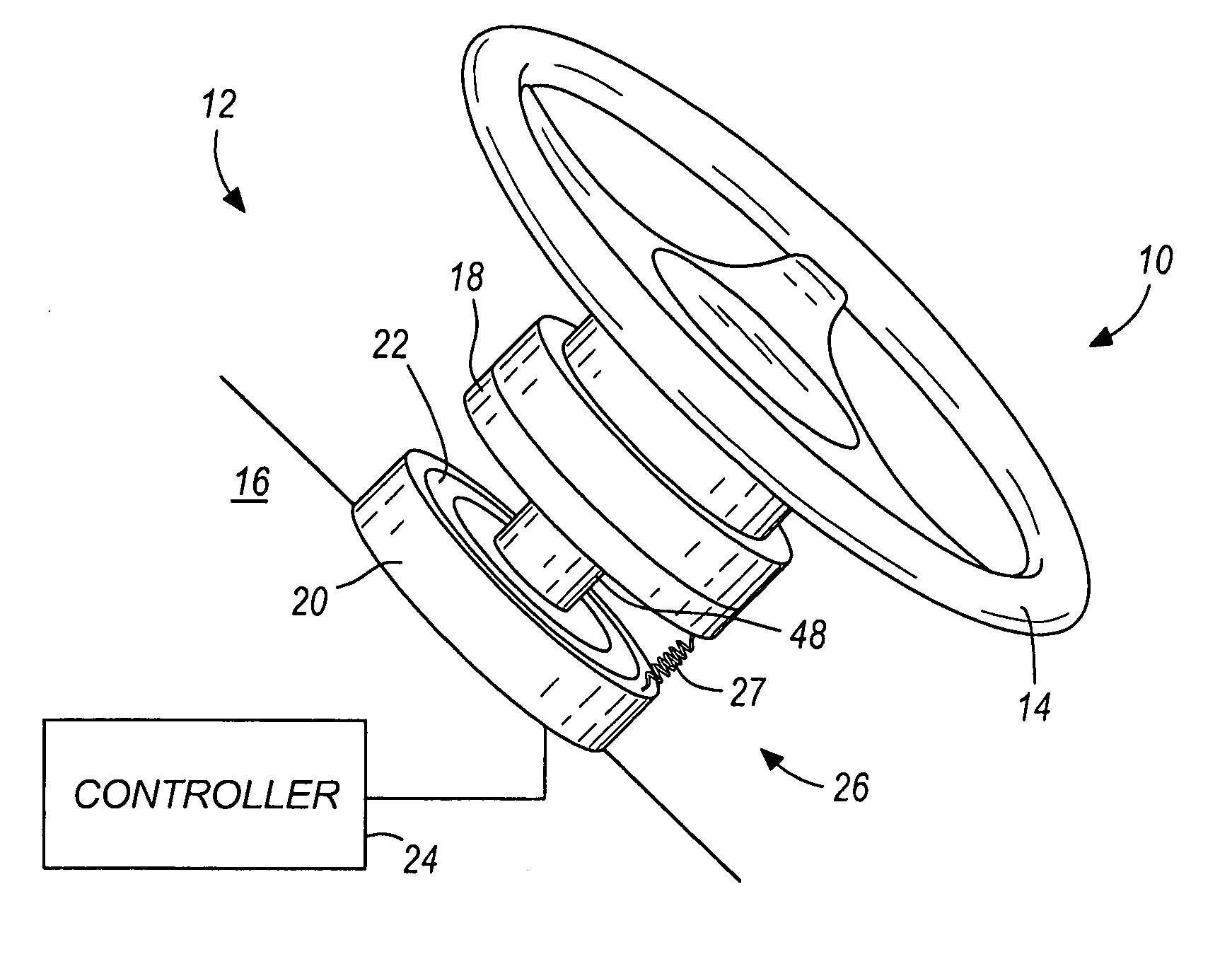
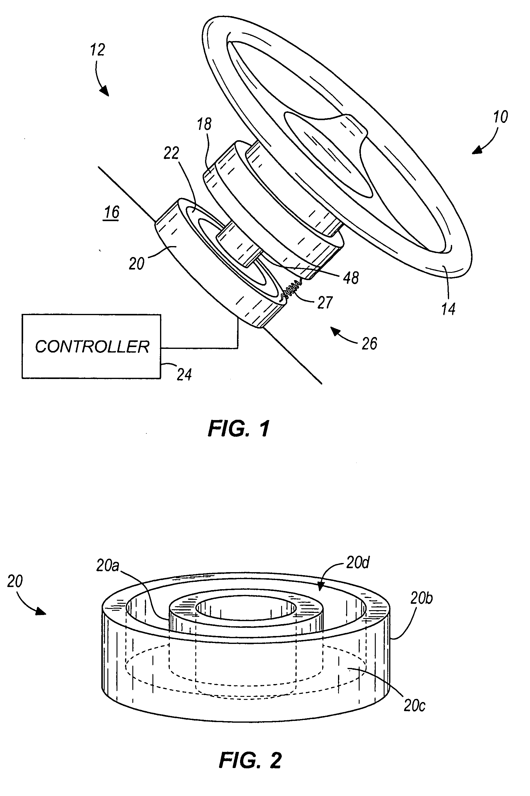
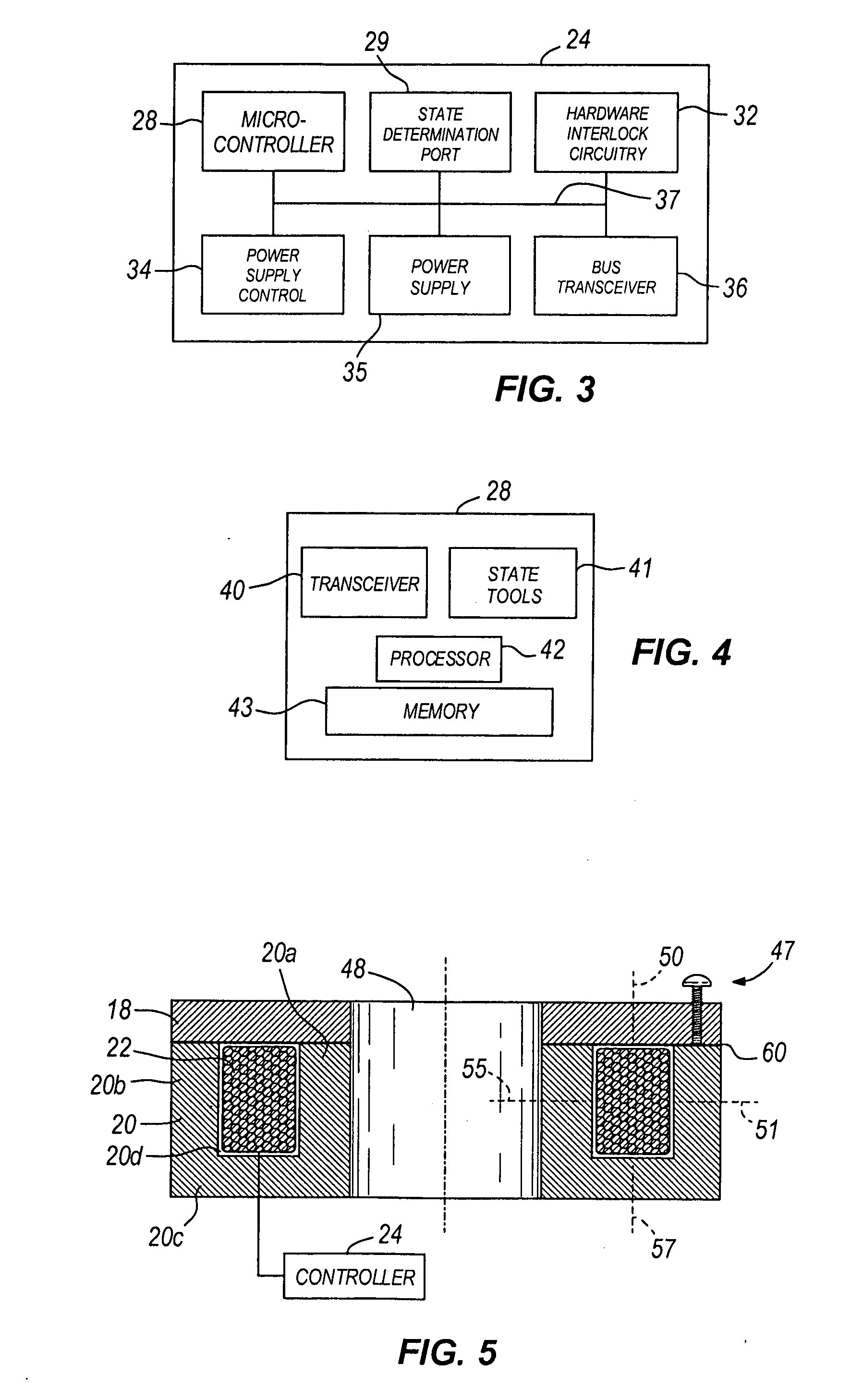
[0003] Some embodiments of the invention provide a solution to retaining an armature engaged with a core housing without requiring current or power. Using a residual magnetic force, power can be provided to change the state of the armature and the core housing from an engaged state to a disengaged state, and a residual magnetic force can retain the state of the armature and the core housing without requiring power. In addition, some embodiments of the invention can release or disengage the armature from the core housing by providing a manual release mechanism. The manual release mechanism can increase a separation distance between the armature and the core housing that substantially nulls the residual magnetic force retaining the armature engaged with the core housing.

Problems solved by technology

The residual field of a permanent magnet cannot be easily demagnetized by applying a magnetic field.

Method used


Image

  • Residual magnetic devices and methods
  • Residual magnetic devices and methods
  • Residual magnetic devices and methods

Examples


Embodiment Construction

[0092] Before any embodiments of the invention are explained in detail, it is to be understood that the invention is not limited in its application to the details of construction and the arrangement of components set forth in the following description or illustrated in the following drawings. The invention is capable of other embodiments and of being practiced or of being carried out in various ways. Also, it is to be understood that the phraseology and terminology used herein is for the purpose of description and should not be regarded as limited. The use of “including,”“comprising” or “having” and variations thereof herein is meant to encompass the items listed thereafter and equivalents thereof as well as additional items. The terms “mounted,”“connected” and “coupled” are used broadly and encompass both direct and indirect mounting, connecting and coupling. Further, “connected” and “coupled” are not restricted to physical or mechanical connections or couplings, and can include el...


PUM


Abstract

Residual magnetic locks, brakes, rotation inhibitors, clutches, actuators, and latches. The residual magnetic devices can include a core housing and an armnature. The residual magnetic devices can include a coil that receives a magnetization current to create an irreversible residual magnetic force between the core housing and the armature.

Description

RELATED APPLICATIONS [0001] The present application is a continuation-in-part of co-pending U.S. application Ser. No. 11 / 094,787, U.S. application Ser. No. 11 / 094,800, U.S. application Ser. No. 11 / 093,739, U.S. application Ser. No. 11 / 094,801, U.S. application Ser. No. 11 / 094,818, U.S. application Ser. No. 11 / 093,721, U.S. application Ser. No. 11 / 093,761, U.S. application Ser. No. 11 / 094,843, U.S. application Ser. No. 11 / 094,786, U.S. application Ser. No. 11 / 094,802, and U.S. application Ser. No. 11 / 094,804 all filed on Mar. 30, 2005, and U.S. application Ser. No. 11 / 280,983 filed on Nov. 16, 2005, the entire contents of which are all herein incorporated by reference.BACKGROUND [0002] Residual magnetism occurs in materials that acquire magnetic properties when placed in a magnetic field and retain magnetic properties even when removed from the magnetic field. Residual magnets are often created by placing steel, iron, nickel, cobalt, or other soft magnetic materials in a magnetic fie...

Claims


Application Information

Patent Timeline
Patent Type & Authority Applications(United States)
IPC IPC(8): F16D27/00F16D65/28
CPCB60R25/021H02K33/02B60R25/08E05B47/0004E05B47/0005E05B47/0006E05B47/02E05B53/008E05B81/00E05B81/08E05B81/14E05B85/26E05B2047/0073E05B2047/0076E05C17/003E05C19/166F16D27/004F16D27/025F16D27/06F16D63/006F16D65/186F16D2121/20F16D2125/36H01F7/04H01F7/08H01F7/121H01F13/00B60R25/02147
Inventor ORGANEK, GREGORY J.
Owner STRATTEC SECURITY
Why Eureka
Try Eureka