Filter system with canister filter element

a filter system and filter element technology, applied in the field of fluid filters, can solve the problems of contaminating the direct surroundings of the filter element, changing the filter element, and affecting the operation of the filter system, so as to achieve precise radial and axial association, facilitate maintenance, and the effect of precise insertion

Inactive Publication Date: 2006-10-05
MANN HUMMEL GMBH
View PDF16 Cites 58 Cited by
  • Summary
  • Abstract
  • Description
  • Claims
  • Application Information

AI Technical Summary

Benefits of technology

[0014] In accordance with another embodiment of the invention, the support contours form discharge volumes between the filter bellows and the inside of the liquid-tight casing, such that the discharge volumes communicate with the floor of the liquid-tight casing. As a result, the liquid cleaned by the filter bellows can flow through the discharge volumes to the floor of the liquid-tight casing. Apart from these advantages, i.e., greater ease of maintenance and the function of an external support member, a third advantage is achieved, i.e., the possibility of using the support member to receive and transfer a liquid.
[0015] In accordance with yet another advantageous embodiment of the invention, the liquid-tight casing has at least one active contour in the region of one of the end faces, extending radially beyond the circumferential diameter. This active contour enables, for example, a precise radial and axial association or positioning relative to the cup-shaped housing. The active contour also makes it possible to check whether a filter element is inserted and whether the inserted filter element is suitable for the filter system.
[0016] Advantageously, the active contour is designed to communicate with a recess in the cup-shaped housing. Because no liquid is present outside the filter element, the filter element can be easily inserted into the cup-shaped housing and axially and radially fixed without a special seal being required.
[0017] According to another advantageous embodiment of the inventive concept, an integral anti-drain membrane or back-flow check membrane is disposed in the region of the liquid inlet and outlet. This integral anti-drain membrane functions as a normal anti-drain memb

Problems solved by technology

This has drawbacks, however, resulting from the material mix of the filter because a mixture of plastics, paper, and metal must be disposed of, and material separation for disposal is problematic.
The drawback of this arrangement lies in the changing of the filter element.
First, there is a risk of contamination of

Method used


Image

  • Filter system with canister filter element
  • Filter system with canister filter element
  • Filter system with canister filter element

Examples


Embodiment Construction

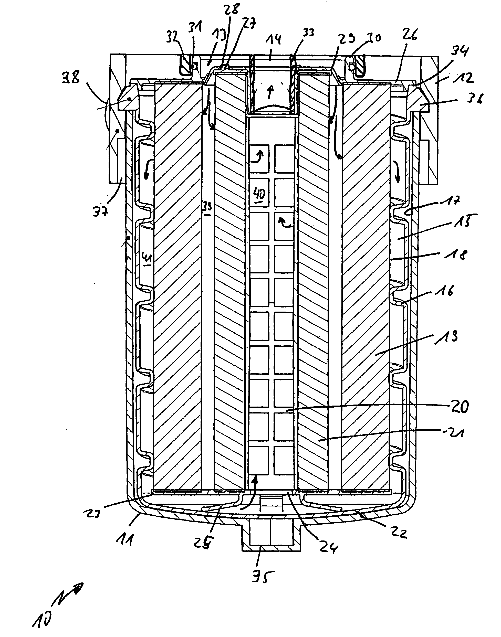
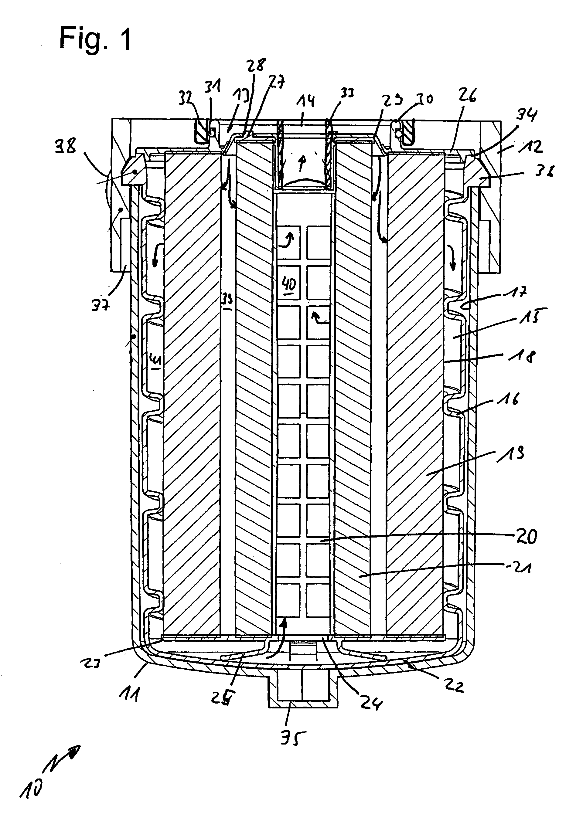
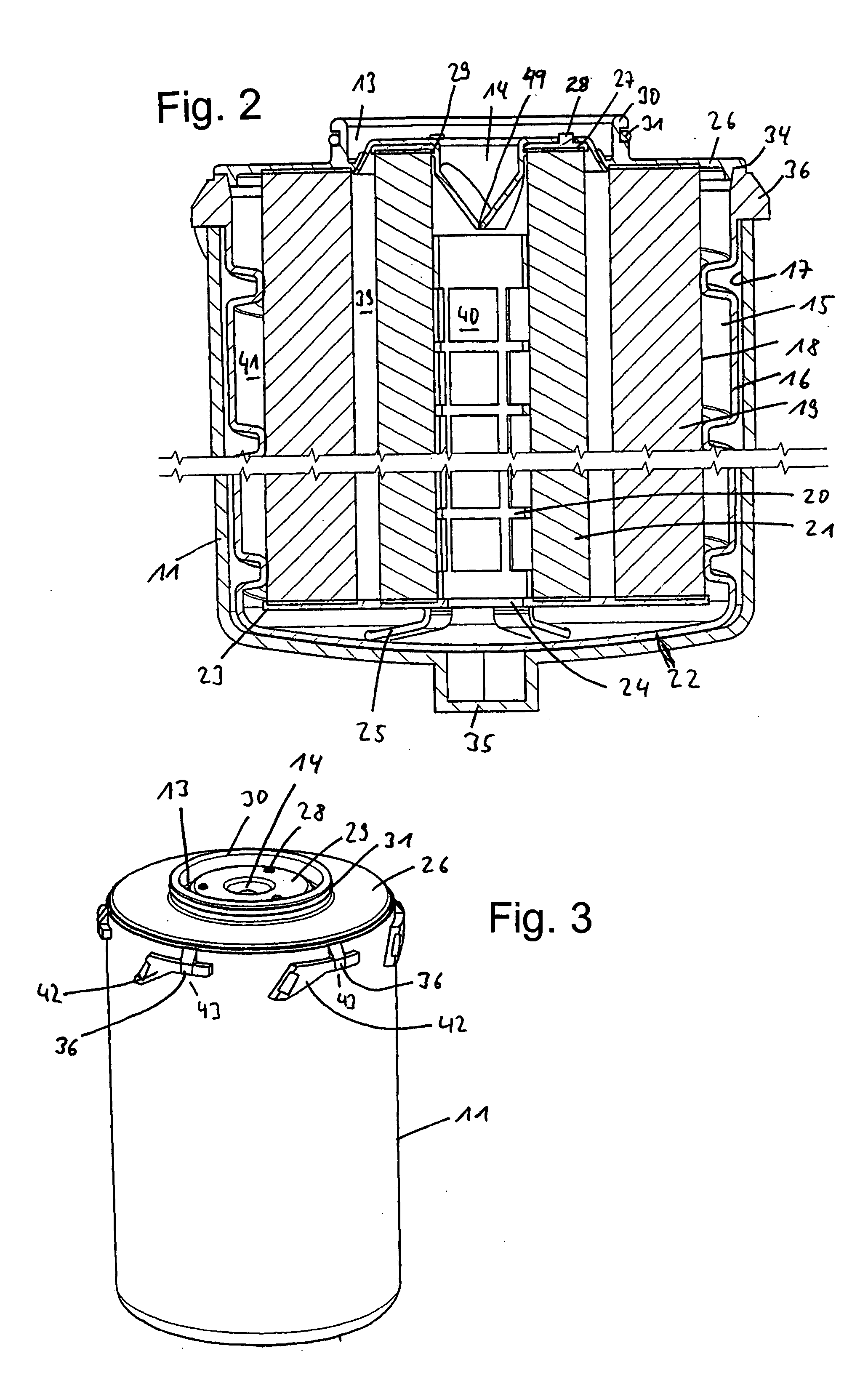
[0034]FIG. 1 is a sectional view of a liquid filter system 10 in which a cup-shaped housing 11 is connected to a connection head by a bayonet connection. The connection head 12 may be a separate connecting flange, or it may be formed directly from an internal combustion engine component. The filter system is suitable for liquids of any kind used in an internal combustion engine, such as oils, fuels, hydraulic fluids, or coolants. An inlet 13 and an outlet 14 are disposed in the connection head 12 of the filter system 10. The outlet 14 is arranged concentrically in the center of the connection between the cup-shaped housing 11 and the connection head 12. The inlet 13 is distributed concentrically around the outlet 14, also in the interior of the connection between the cup-shaped housing 11 and the connection head 12.

[0035] Inside the cup-shaped housing 11 is a filter element 15. The filter element 15 comprises a canister 16 which holds the filter medium or media. The circumference o...


PUM

PropertyMeasurementUnit
Diameteraaaaaaaaaa
Volumeaaaaaaaaaa
Circumferenceaaaaaaaaaa

Abstract

A filter system for a fluid, particularly a liquid filter, especially an oil filter for an internal combustion engine, having a receiving head, a cup-shaped housing releasably connectable to the receiving head, and a replaceable filter element disposed the cup-shaped housing, in which the filter element has a liquid-tight casing which is received in the interior of the cup-shaped housing.

Description

BACKGROUND OF THE INVENTION [0001] The present invention relates to a fluid filter, particularly a liquid filter, especially an oil filter for an internal combustion engine, comprising a receiving head, a cup-shaped housing releasably connectable to the receiving head, and a replaceable filter element disposed in the cup-shaped housing. [0002] Two major types of fluid filters, particularly oil filters for internal combustion engines, are known in the art. The first major type comprises so-called spin-on filters. A spin-on filter has a cup-shaped housing, a filter element non-releasably disposed therein, and a threaded end plate. The cup-shaped housing is made of metal, so that it can withstand the pressure pulsation which occurs in the interior of the filter during operation of the internal combustion engine. The spin-on filter is screwed onto a receiving flange, or directly onto the engine block of the internal combustion engine, and during servicing is completely replaced with a n...

Claims


Application Information

Patent Timeline
IPC IPC(8): B01D35/28
CPCB01D27/08B01D29/21B01D35/153B01D2201/0415B01D2201/307B01D2201/4015B01D27/144B01D29/232B01D29/54B01D35/30B01D2201/295
Inventor DWORATZEK, KLEMENSBAUDER, RALFMUENKEL, KARLHEINZNGUYEN, DUC CUONG
Owner MANN HUMMEL GMBH
Why Eureka
Try Eureka