Aperture and projection lens system

Active Publication Date: 2006-10-05
AIXIN TECH
View PDF4 Cites 9 Cited by
  • Summary
  • Abstract
  • Description
  • Claims
  • Application Information

AI Technical Summary

Benefits of technology

[0010] In view of the above, an object of the present invention is to provide an

Problems solved by technology

However, the diameters of the spots affect the image quality, and the diameter of the spot of the blue light shown in FIG. 2A is too large to produce desired image

Method used


Image

  • Aperture and projection lens system
  • Aperture and projection lens system
  • Aperture and projection lens system

Examples


Example

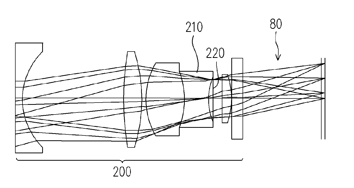
[0027]FIG. 4A is a schematic structure diagram for illustrating a projection lens system according to an embodiment of the present invention and FIG. 4B is a structure diagram for illustrating an aperture of FIG. 4A. Referring to FIGS. 4A and 4B, a projection lens system 200 according to the embodiment of the present invention comprises at least one lens 210 and an aperture 220. The aperture 220 is disposed in front of the lens 210. The aperture 220 comprises a round filter portion 222 and at least one annular filter portion 224. The round filter portion 222 and the annular filter portion 224 are forming a round zone. A transmission wavelength range of the round filter portion 222 is larger than a transmission wavelength range of the annular filter portion 224.

[0028] The optical lens system 200 is illustrated as a projection lens system for example, being adapted to project beams 80 onto a screen (not shown) for forming images. However, the projection lens system of the embodiment ...


PUM


Abstract

An aperture comprising a round filter portion and at least one annular filter portion is provided. The round filter portion and the annular filter portion are forming a round zone. A transmission wavelength range of the round filter portion is larger than a transmission wavelength range of the annular filter portion. A projection lens system with the aperture can produce images having higher brightness of the images and better image quality.

Description

CROSS-REFERENCE TO RELATED APPLICATION [0001] This application claims the priority benefit of Taiwan application serial no. 9411 0687, filed on Apr. 4, 2005. All disclosure of the Taiwan application is incorporated herein by reference. BACKGROUND OF THE INVENTION [0002] 1. Field of the Invention [0003] The present invention relates to an aperture and a projection lens system, and particularly to an aperture having a plurality of filter portions and a projection lens system having the aperture. [0004] 2. Description of Related Art [0005]FIG. 1A is a diagram for illustrating a structure of a conventional projection lens system 100, and FIG. 1B is a diagram for illustrating a structure of an aperture 120 shown in FIG. 1A. Referring to FIGS. 1A and 1B, the conventional projection lens system 100 comprises a plurality of lenses 110 and the aperture 120, the aperture 120 being disposed among the lenses 110. The projection lens system 100 is adapted to project beams 80 onto a screen (not s...

Claims


Application Information

Patent Timeline
IPC IPC(8): G02B7/00
CPCG02B5/005G02B27/58G02B5/20
Inventor LIU, CHIN-KU
Owner AIXIN TECH
Why Eureka
Try Eureka