Electrodynamic loudspeaker
- Summary
- Abstract
- Description
- Claims
- Application Information
AI Technical Summary
Benefits of technology
Problems solved by technology
Method used
Image
Examples
embodiment 1
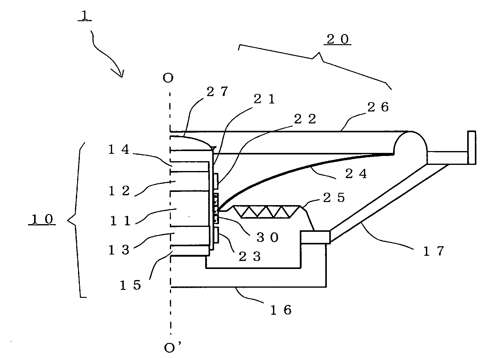
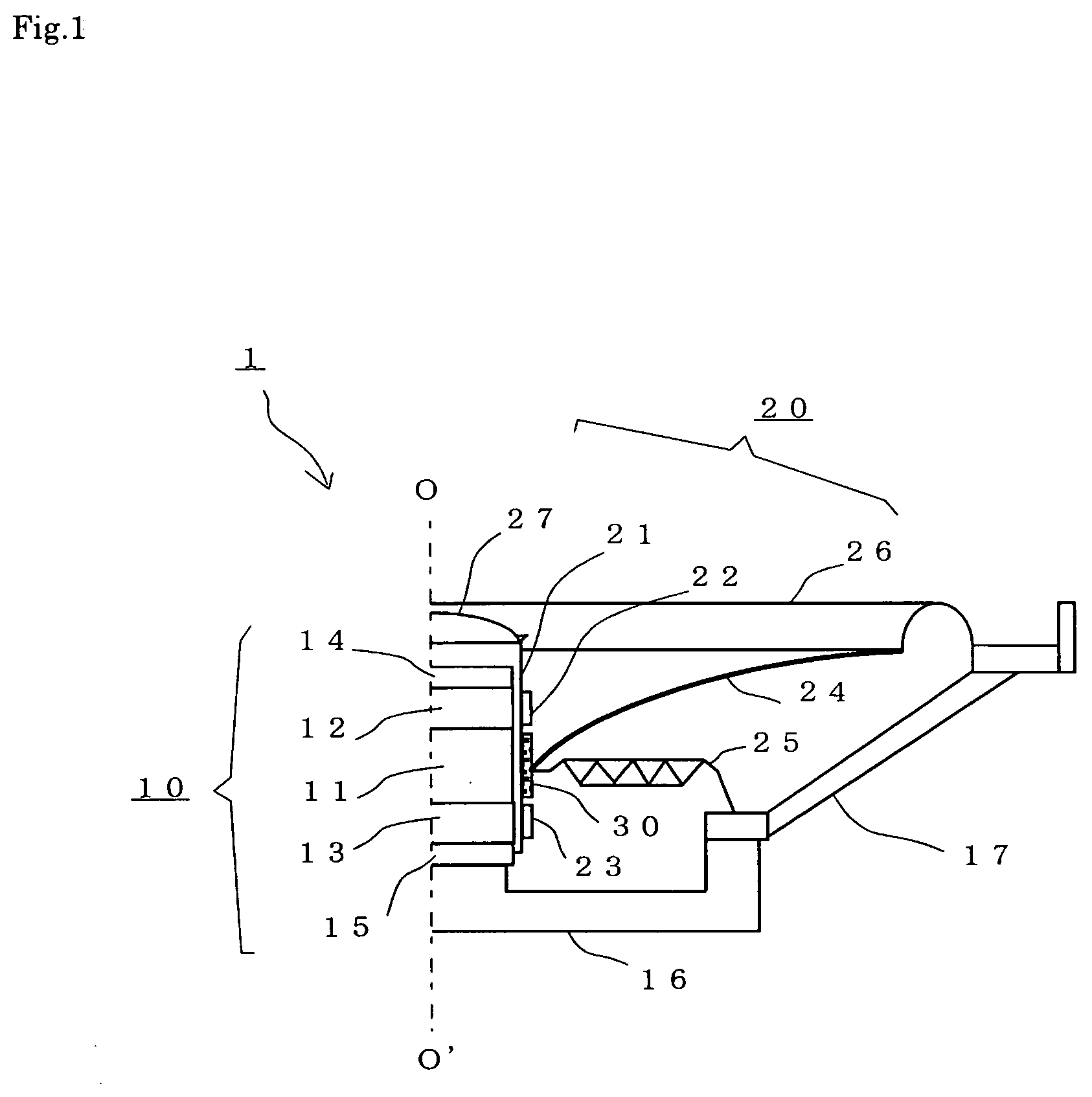
[0030]FIG. 1 is a schematic cross-sectional view showing an electrodynamic loudspeaker 1 according to a preferred embodiment of the present invention, while omitting the left half of the loudspeaker being generally in axial symmetry about the center axis O-O′. The electrodynamic loudspeaker 1 of the present embodiment is of a so-called “2-voice coil type” and includes a magnetic circuit 10 including a magnet and a vibrator 20 including two voice coils, which are fixed to a base 16 and a frame 17. The total weight of the electrodynamic loudspeaker is reduced by reducing the weight of the magnetic circuit 10.
[0031] Specifically, the magnetic circuit 10 includes a magnet 11, a first pole 12 adhering to the upper surface of the magnet 11, a second pole 13 adhering to the lower surface of the magnet 11, a magnet 14 adhering to the upper surface of the first pole 12, and a magnet 15 adhering to the lower surface of the second pole 13. Thus, the magnetic circuit 10 is an open-type magneti...
embodiment 2
[0041]FIG. 4 is a schematic cross-sectional view showing an electrodynamic loudspeaker 4 according to another preferred embodiment of the present invention, while omitting the left half of the loudspeaker being generally in axial symmetry about the center axis O-O′. The electrodynamic loudspeaker 4 of the present embodiment includes a magnetic circuit 40 including a magnet and the vibrator 20 including two voice coils, in which the total weight of the electrodynamic loudspeaker is reduced by reducing the weight of the magnetic circuit 40. Like elements to those of the electrodynamic loudspeaker 1 of Embodiment 1, e.g., the base 16, the frame 17 and the cone diaphragm 24 of the vibrator 20, will not be further described below.
[0042] Specifically, the magnetic circuit 40 includes a magnet 41, a first pole 42 adhering to the upper surface of the magnet 41, and a second pole 43 adhering to the lower surface of the magnet 41. Thus, the magnetic circuit 40 is also an open-type magnetic c...
embodiment 3
[0046]FIG. 5 is a schematic cross-sectional view showing an electrodynamic loudspeaker 5 according to another preferred embodiment of the present invention, while omitting the left half of the loudspeaker being generally in axial symmetry about the center axis O-O′. The electrodynamic loudspeaker 5 of the present embodiment includes a repulsion-type magnetic circuit 50 including two magnets, and the vibrator 20 including one voice coil, in which the total weight of the electrodynamic loudspeaker is reduced by reducing the weight of the repulsion-type magnetic circuit 50. As in Embodiment 2, like elements to those of the electrodynamic loudspeaker 1 of Embodiment 1, e.g., the base 16, the frame 17 and the cone diaphragm 24 of the vibrator 20, will not be further described below.
[0047] Specifically, the repulsion-type magnetic circuit 50 includes a pole 51, a first magnet 52 adhering to the upper surface of the pole 51, and a second magnet 53 adhering to the lower surface of the pole...
PUM
 Abstract
Description
Claims
Application Information
 - R&D
- Intellectual Property
- Life Sciences
- Materials
- Tech Scout
- Unparalleled Data Quality
- Higher Quality Content
- 60% Fewer Hallucinations
Browse by: Latest US Patents, China's latest patents, Technical Efficacy Thesaurus, Application Domain, Technology Topic, Popular Technical Reports.
© 2025 PatSnap. All rights reserved.Legal|Privacy policy|Modern Slavery Act Transparency Statement|Sitemap|About US| Contact US: help@patsnap.com


