
Ball Connecting Body for a Rolling Motion Apparatus

Active Publication Date: 2006-10-05
HIWIN TECH
View PDF7 Cites 2 Cited by
  • Summary
  • Abstract
  • Description
  • Claims
  • Application Information

AI Technical Summary

Benefits of technology

[0007] The primary objective of the present invention is to provide a ball connecting body for a rolling motion apparatus, thereby preventing the balls from colliding and rubbing each other.
[0011] the connecting member, connects two adjacent spacers, a total width of the connecting member in a direction of the connecting line of the two guide linking members is smaller than a total height of the connecting member in a direction vertical to the connecting line of the two guide linking members, so that the connecting member has an excellent bendable capability in the direction of the connecting line of the two guide linking members.

Problems solved by technology

During the rotation process of the balls, the balls mutually collide and rub, thereby producing noise and causing inconvenience of operation.
However, when applied to the rotating ball bearing, the linear guide-way or the ball screw, the ball connecting body cannot be bent in an arbitrary direction of the three-dimensional path due to its belt-shaped design, so that the ball circulation system is only moved along the two-dimensional plane, and cannot move along the three-dimensional path, for example, U.S. Pat. No., 2,366,120, 5,429,439, 5,562,346, and 5,758,975, thereby greatly limiting the circulation design of the linear guide-way and the ball screw.
However, it is difficult to bend the belt-shaped ball connecting body, while the returning radius is apparently enlarged, thereby increasing the space of the returning path, so that the conventional belt-shaped ball connecting body cannot completely satisfy the requirements of the industry.

Method used


Image

  • Ball Connecting Body for a Rolling Motion Apparatus
  • Ball Connecting Body for a Rolling Motion Apparatus
  • Ball Connecting Body for a Rolling Motion Apparatus

Examples


first embodiment

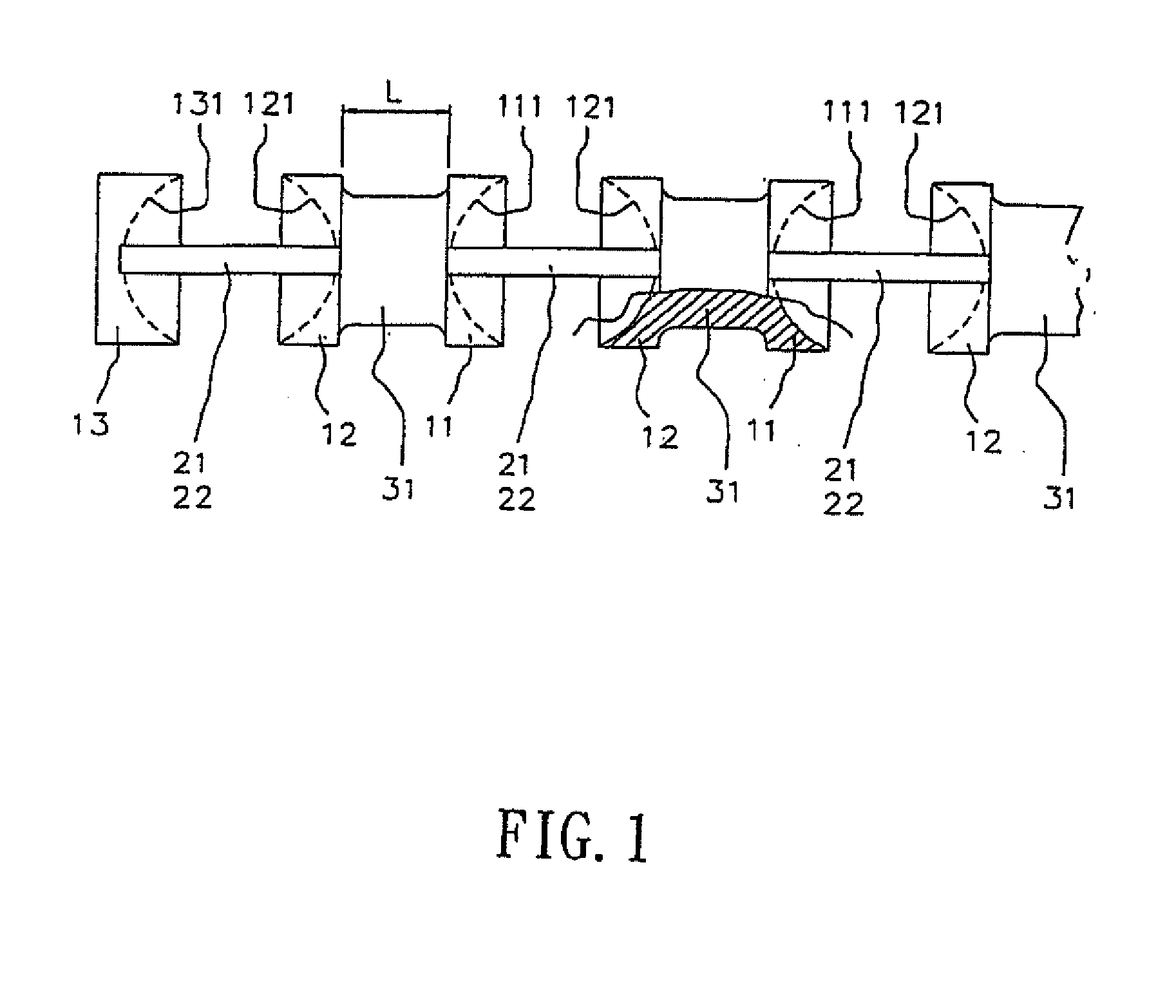
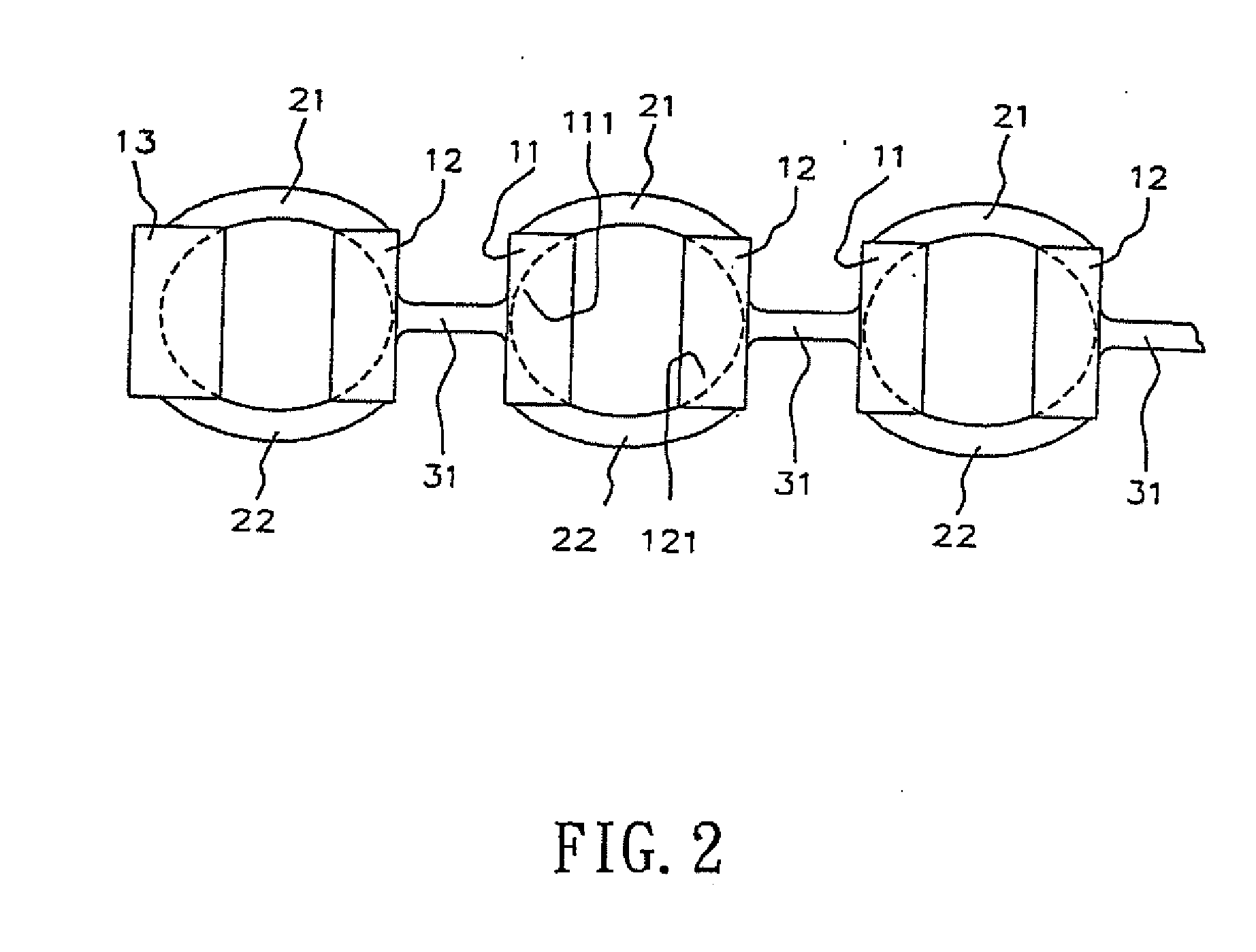
[0028] Referring to the drawings and initially to FIGS. 1-3, a ball connecting body for a rolling motion apparatus in accordance with the present invention primarily comprises spacers, guide linking members, and connecting members.

[0029] The spacers 11 and the spacers 12 are arranged in a staggered manner, for separating two adjacent balls, so that they do not contact each other, and so that the ball connecting body may move with the balls. The guide linking members 21 and 22 are arranged in pairs with each pair being arranged horizontally. The guide linking members 21 and 22 are located at the two sides of the ball for linking the spacers 11 and its right side adjacent spacers 12, so that the ball is maintained in a space formed by the guide linking members and the spacers. The guide linking members 21 and 22 can be rotated about a horizontal axis relative to the two spacers simultaneously as can be seen in FIGS. 12 and 13, thereby preventing the spacers 11 and the adjacent spacers...

second embodiment

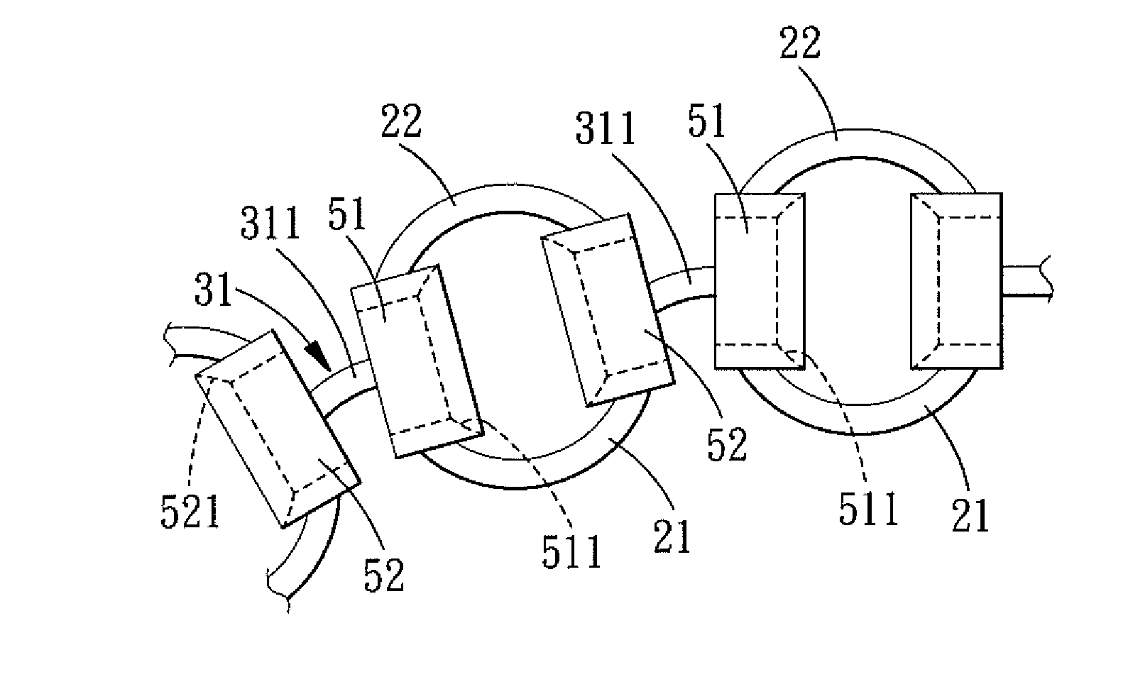
[0034] Referring to FIGS. 7 and 8, in accordance with the present invention, each of the spacers 51, 52 and 53 is designed to have a hollow ring shape, and is respectively formed with a ball retaining face 511, 521 and 531. By the ring-shaped hollow design, the lubricating oil may flow more conveniently, thereby providing a better lubrication and heat transfer effect to the ball 4. The connecting member 31 is a solid rectangular body.

third embodiment

[0035]FIGS. 9, 10, and 12-15 show a ball connecting body in accordance with the present invention. The connecting member 31 of FIG. 7 crosses the hollow portion of the center of the spacers 51 and 52, thereby forming a baffle to affect flow of the lubricating oil. For facilitating flow of the lubricating oil, as shown in FIGS. 9, 10, 12, 13, 14 and 15 the connecting member 31 is a hollow structure having two parallel bar-shaped connecting bars 311 and 312. It is hollow between the two bar-shaped connecting bars 311 and 312. The two bar-shaped connecting bars 311 and 312 are used to connect the spacers 51 and 52. Thus, the cross-sectional shape of the two connecting bars 311 and 312 may be circular, square or the like without any limitation. As shown in FIG. 10, the distance H between the outer surfaces of the two connecting bars 311 and 312 is greater than the width W of the respective connecting bars 311 and 312, such that the connecting member 31 is more bendable horizontally than...


PUM


Abstract

A ball connecting body for a ball screw or a linear guide-way, comprises spacers, guide linking members, and connecting members. The spacers are interposed between two adjacent balls, thereby preventing the two balls from hitting. The guide linking members are used for linking the two spacers, so that the ball may be maintained in a space formed by the guide linking members and the spacers. The connecting member connects two adjacent spacers. The total width of the connecting member in a direction of a connecting line of the two guide linking members is smaller than the total height of the connecting member in a direction vertical to the connecting line of the two guide linking members, so that the connecting member has an excellent bendable capability in the direction of the connecting line of the two guide linking members.

Description

BACKGROUND OF THE INVENTION [0001] This application is a continuation of part of U.S. patent application Ser. No. 10 / 833,662 filed on Apr. 27, 2004, which claims the benefit of the earlier filing date. [0002] 1. Field of the Invention [0003] The present invention relates to a ball connecting body for a rolling motion apparatus, and more particularly to a ball connecting body for a ball screw or a linear guide-way, thereby preventing the balls from colliding and rubbing each other. Especially, the ball connecting body of the present invention has a multi-directional bendable function by the special design of the connecting member. [0004] 2. Description of the Related Art [0005] A conventional linear guide-way and ball screw employ rolling members, such as balls or rollers, to function as a force-transmitting medium, and application of the balls is the most popular. During the rotation process of the balls, the balls mutually collide and rub, thereby producing noise and causing inconv...

Claims


Application Information

Patent Timeline
IPC IPC(8): F16C19/00
CPCF16C29/06Y10T74/19777F16H25/2238F16C33/3825
Inventor KUO, CHANG-HSIN
Owner HIWIN TECH
Features
  • Generate Ideas
  • Intellectual Property
  • Life Sciences
  • Materials
  • Tech Scout
  • Unparalleled Data Quality
  • Higher Quality Content
  • 60% Fewer Hallucinations
Learn More