Liquid injection needle element capable of jetting a liquid in a predetermined angle range and method of producing the same

Inactive Publication Date: 2006-10-05
MATSUMOTO DENTAL UNIVERSITY
View PDF11 Cites 35 Cited by
  • Summary
  • Abstract
  • Description
  • Claims
  • Application Information

AI Technical Summary

Benefits of technology

[0018] It is therefore an object of this invention to provide a liquid injection needle element which is

Problems solved by technology

Therefore, when the liquid is applied with pressure to be jetted, the operator's fingers may be undesiredly moved.
In this event, the liquid can not accurately be directed to a predetermined jet position at a treated part.
As a consequence, the treated part can not properly and quickly be treated.
In this event, it is impossible to jet the liquid to an entire area of a gap between the tooth and the gingiva and to sufficiently supply the liquid over lateral surfaces of the tooth and the gingiva opposite to each other.
In this event, the treated part may possibly be damaged by excessive plunging.
Thus, the safety of a patient can not be assured.
Further, the cannula in each of the Patent Documents 1 and 2 is not adapted to cleaning of a dental root furcation present in a multi-rooted tooth having two or more dental roots and cleaning of a per

Method used


Image

  • Liquid injection needle element capable of jetting a liquid in a predetermined angle range and method of producing the same
  • Liquid injection needle element capable of jetting a liquid in a predetermined angle range and method of producing the same
  • Liquid injection needle element capable of jetting a liquid in a predetermined angle range and method of producing the same

Examples


first embodiment

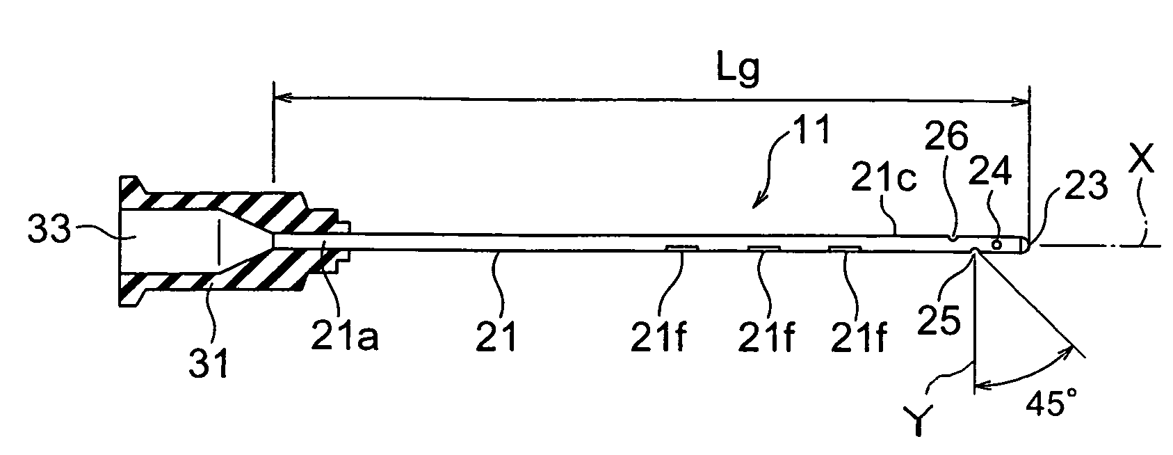
[0061] Referring to FIGS. 1 through 4, a liquid injection needle element 11 according to this invention comprises a cylindrical cannula 21 and a needle hub 31 holding the cannula 21.

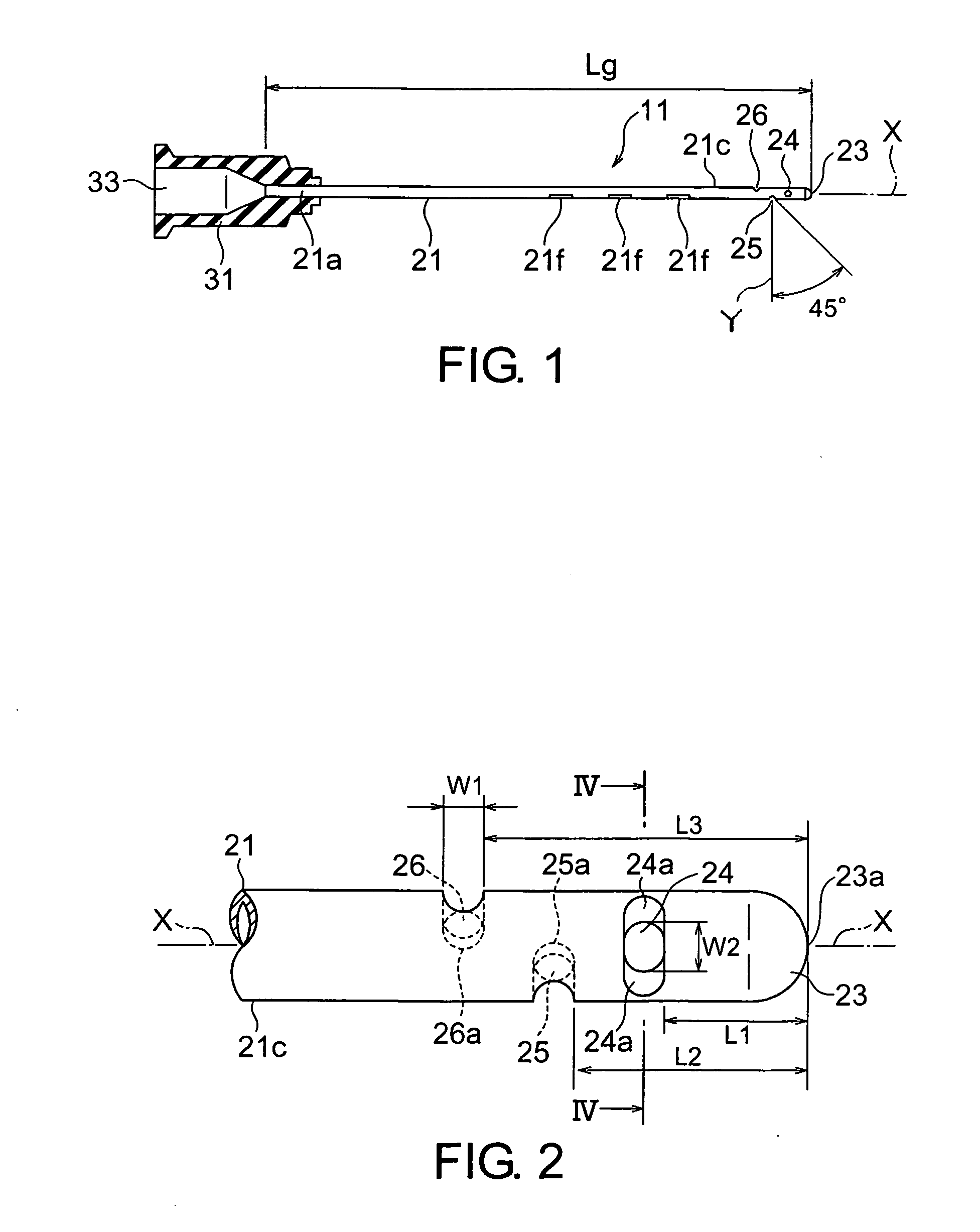
[0062] The cannula 21 is made of a metal material and has a base 21a and a front part 21c opposite to the base 21a. The base 21a is supported by the needle hub 31. The front part 21c has a forward end portion 23 as a closed end. The forward end portion 23 has a semispherical outer surface. The front part 21c of the cannula 21 is provided with a first nozzle orifice 24, a second nozzle orifice 25, and a third nozzle orifice 26 formed on a lateral wall thereof.

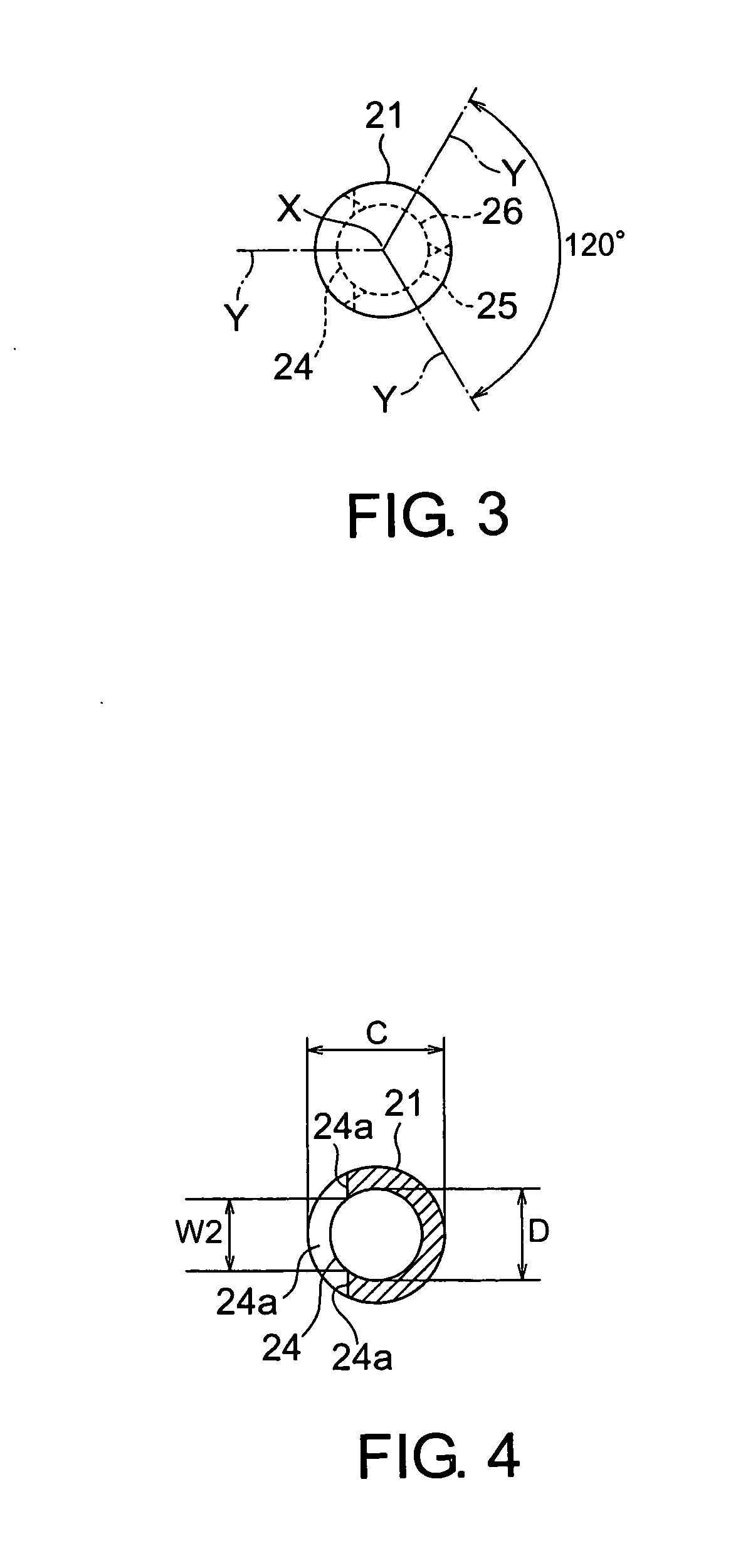
[0063] The first through the third nozzle orifices 24, 25, and 26 are spaced from one another in a direction of a center axis X of the cannula 21. Each of the first through the third nozzle orifices 24, 25, and 26 has an orifice axis Y perpendicular to the center axis X. The first through the third nozzle orifices 24, 25, and 26 are also spaced from...

second embodiment

[0084] Referring to FIGS. 5 and 6, description will be made of a liquid injection needle element according to this invention. Similar parts are designated by like reference numerals and description thereof will be omitted.

[0085] As illustrated in the figures, the cannula 21 has only the first and the second nozzle orifices 24 and 25 without the third nozzle orifice 26. The first and the second nozzle orifices 24 and 25 are formed on the lateral wall of the cannula 21 at its front part and at positions different from each other in the direction of the center axis X of the cannula 21. The first and the second nozzle orifices 24 and 25 are spaced from each other in the circumferential direction of the lateral wall around the center axis X so that the orifice axes Y are spaced by 180 degrees from each other.

[0086] In the cannula 21 in the second embodiment, when the forward end portion 23 of the cannula 21 is directed downward, the liquid can be jetted from each of the first and the se...

third embodiment

[0087] Referring to FIGS. 7 and 8, description will be made of a liquid injection needle element according to this invention. Similar parts are designated by like reference numerals and description thereof will be omitted.

[0088] The cannula 21 has a fourth nozzle orifice 27 in addition to the first through the third nozzle orifices 24, 25, and 26 in the first embodiment. The first through the fourth nozzle orifices 24 through 27 are formed on the lateral wall of the cannula 21 at its front part 21c and at positions different from one another in the direction of the center axis X of the cannula 21. The first through the fourth nozzle orifices 24 through 27 are spaced from each other in the circumferential direction around the center axis X so that the orifice axes Y are spaced by 90 degrees from one another.

[0089] The fourth nozzle orifice 27 is same in shape as the first through the third nozzle orifices 24, 25, and 26. The fourth nozzle orifice 27 is formed at a distance L4 of 1.9...


PUM

PropertyMeasurementUnit
Pressureaaaaaaaaaa
Pressureaaaaaaaaaa
Angleaaaaaaaaaa

Abstract

A cannula has a front part in a direction of a center axis X with its forward end portion closed. The front part has a plurality of nozzle orifices each of which has an orifice axis Y intersecting the center axis X. Each of the nozzle orifices has a first diameter in a first direction parallel to the center axis X and a second diameter in a second direction perpendicular to the first direction. The first diameter ranges between 0.1 mm and 0.5 mm while the second diameter ranges between 0.1 mm and 0.3 mm so that a liquid in the cannula is jetted from the nozzle orifices in an angle range of 45 degrees towards the forward end portion with respect to the orifice axis.

Description

[0001] This application claims priority to prior Japanese patent application JP 2005-94503, the disclosure of which is incorporated herein by reference. BACKGROUND OF THE INVENTION [0002] This invention relates to a liquid injection needle element capable of jetting a liquid in a cannula or needle tube to the outside of the cannula and a method of producing the same. [0003] In the dental practice or treatment, a tooth is often ground. After the tooth is ground, grinding chips left around the tooth sometimes enter a small gap at the bottom of the tooth or in a root canal of the tooth. Those grinding chips are removed by jetting a liquid (cleaning liquid) from a cannula. [0004] In the dental treatment, the cannula is also used when a periodontal disease is treated. In this case, a forward end portion of the cannula is inserted into a periodontal pocket (a space between a tooth and a gingiva) which is an affected part of the periodontal disease and the liquid is jetted from the cannula...

Claims


Application Information

Patent Timeline
IPC IPC(8): A61C17/02A61C5/02
CPCA61C5/02A61C5/062B21C37/157B05C17/00516A61M5/3291A61C5/40A61C5/62
Inventor KUROIWA, AKIHIROYAMAMOTO, AKIOOTOGOTO, JUNICHIMURAKOSO, TAKAAKIHASEGAWA, HIROSHIYAMAGUCHI, IWAO
Owner MATSUMOTO DENTAL UNIVERSITY
Why Eureka
Try Eureka