
Device for counting cells and method for manufacturing the same

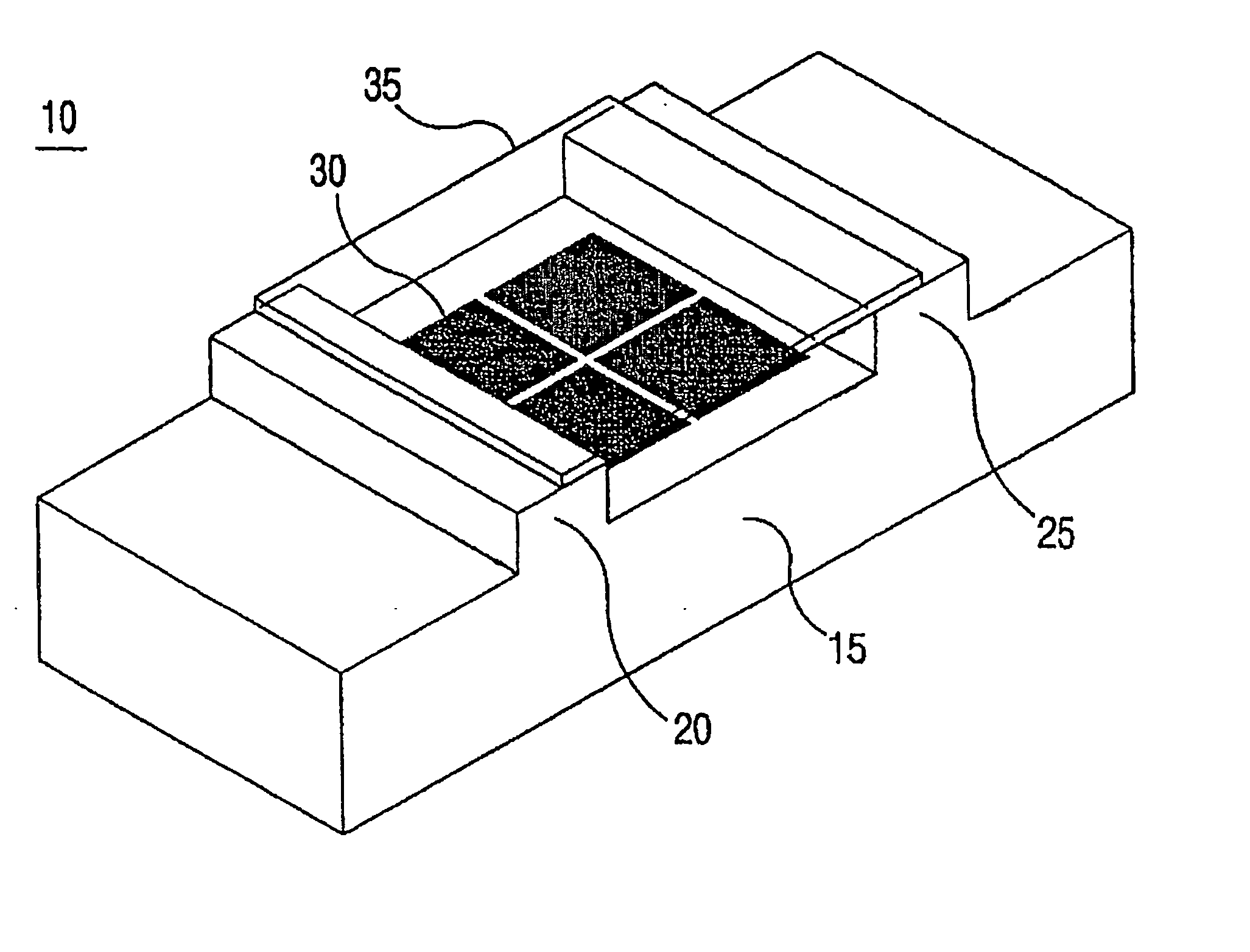
a technology for counting cells and cells, applied in the field of counting cells, can solve the problems of cover damage, sample drop, poor tightness between the cover and the partition wall, etc., and achieve the effect of easy counting of rythrocytes, leukocytes or platelets, and easy counting of microorganisms

Inactive Publication Date: 2006-10-05
DIGITAL BIO TECHNOLOGY CO LTD
View PDF12 Cites 56 Cited by
  • Summary
  • Abstract
  • Description
  • Claims
  • Application Information

AI Technical Summary

Benefits of technology

[0018] When the upper substrate and the lower substrate are integratedly made by bonding them, a covering process as the prior device for counting cells is not required. Accordingly, since it is easy to fill the fill chamber with the sample by dropping the sample into the injection hole, the device can be more easily used than that of the prior art. Also, since the cost of manufacturing the device for counting cells can be greatly decreased, the device can be disposably and easily used.
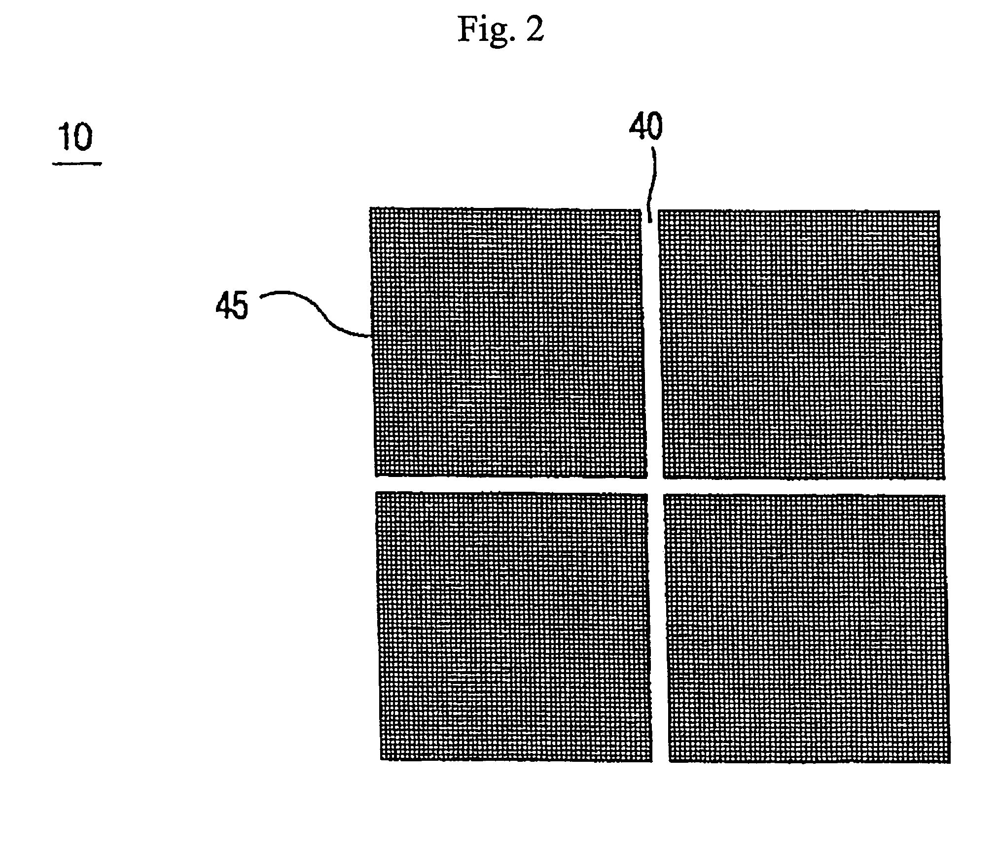
[0025] An indicative member is preferably formed on the upper substrate for indicating a position of the fine lattice patterns. Accordingly, when counting the cells in the sample with a microscope, it is possible to easily find the position of the fine lattice patterns.
[0027] By using the device according to the invention, it is possible to easily count rythrocytes, leukocytes or platelets included in the blood. Additionally, it is possible o easily count microbes which are unicellular organisms, bacteria and any fine articles.

Problems solved by technology

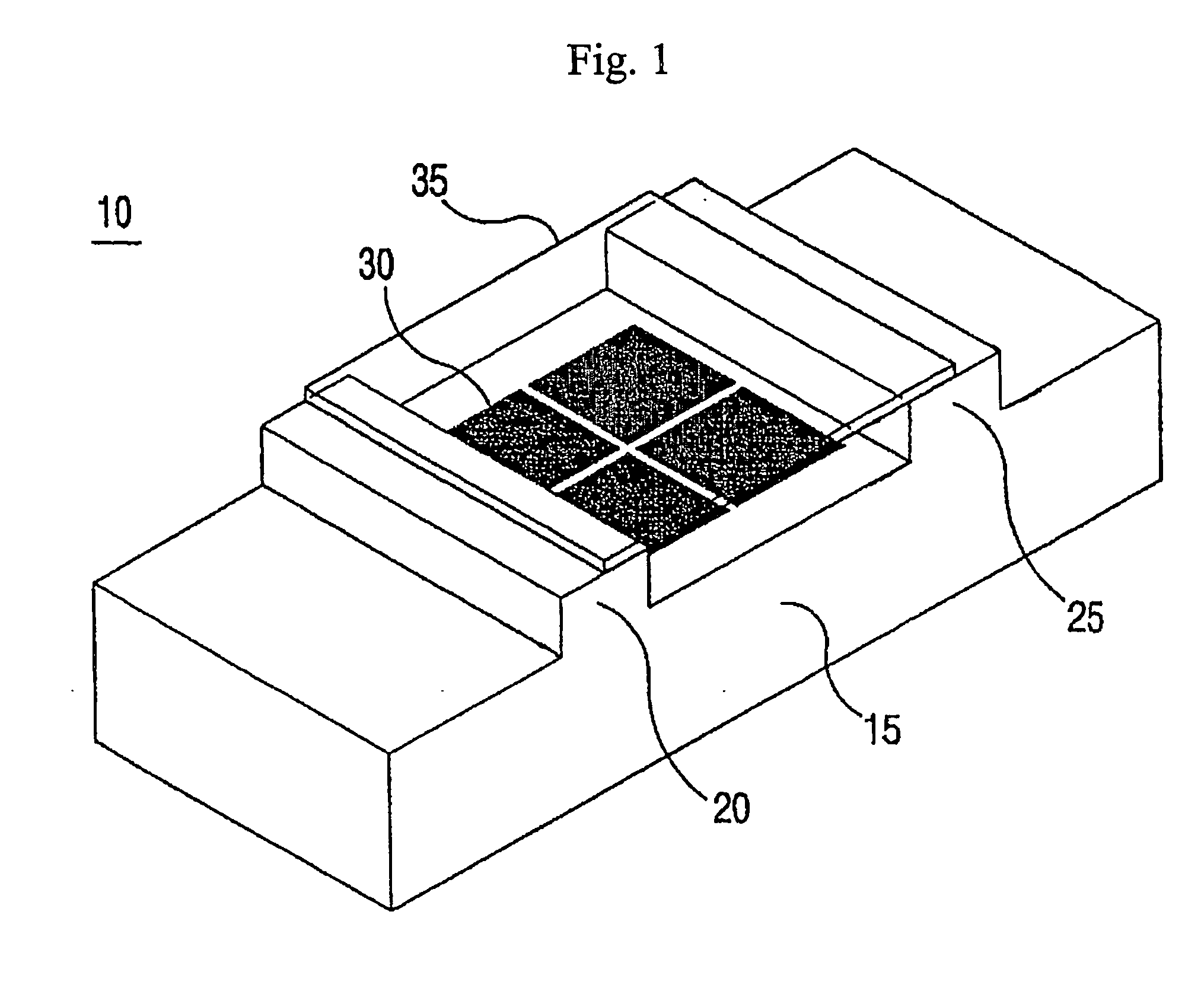
In addition, since the body 15 and the cover 35 are separated, there is troublesomeness that the sample should be dropped after covering the body with the cover.
Particularly, since the tightness between the cover and the partition walls is very poor, it is required that a very strong force should be applied to the cover or the cover should be attached to the partition walls with a separate adhesive.
Also, there is a possibility that the cover is damaged during using the device even if such an additional process was used.

Method used


Image

  • Device for counting cells and method for manufacturing the same
  • Device for counting cells and method for manufacturing the same
  • Device for counting cells and method for manufacturing the same

Examples


Embodiment Construction

[0042] Hereinafter, preferred embodiments of the present invention will be described with reference to the accompanying drawings. In the following description of the present invention, a detailed description of known functions and configurations incorporated herein will be omitted when it may make the subject matter of the present invention rather unclear.

[0043]FIG. 3 is a perspective view showing an upper substrate of a device according to an embodiment of the invention, FIG. 4 is a sectional view of the upper substrate and FIG. 5 is a plan view of the upper substrate.

[0044] As shown in FIGS. 3 to 5, the upper substrate 100 comprises a fill chamber 110 having a predetermined height from a bottom surface of the upper substrate and forming a space for filling a sample, an injecting hole 120 for the sample communicated with the fill chamber and a discharge hole 130 for discharging the air and the excess sample in the fill chamber 110 when injecting the sample. In addition, an indica...


PUM

PropertyMeasurementUnit
heightaaaaaaaaaa
heightaaaaaaaaaa
transparentaaaaaaaaaa

Abstract

Disclosed are a device for counting cells and a method for manufacturing the device. The device comprises a transparent upper substrate and a transparent lower substrate. Fine lattice patterns for counting cells are formed on the lower substrate. A space for filling the sample, including cells, is provided between the upper substrate and the lower substrate. A hole for injecting the samples into the space for filling the samples is provided in the upper substrate. The device is disposable, and the cost of manufacturing the device is low. It is easy to fill the samples into the filling space and to count cells by using the device. The upper substrate and the lower substrate are bonded, and thus, no cover is required.

Description

TECHNICAL FIELD [0001] The present invention relates to a device for counting cells, and in particular to a device for counting cells comprising a transparent lower substrate having fine lattice patterns for counting the cells formed on an upper surface thereof and a transparent upper substrate stacked on the lower substrate, wherein the upper substrate comprises a fill chamber having a predetermined height from a bottom surface of the upper substrate and forming a space for filling a sample including the cells into the fine lattice patterns and an injecting hole for the sample communicated with the fill chamber. BACKGROUND ART [0002] Generally, when diagnosing a disease, it is examined the number and the functions of typical blood cells such as erythrocytes, leukocytes or platelets included in the blood. For example, it is possible to diagnose tuberculosis, obesity or pregnancy from a blood sedimentation rate and dehydration or anemia from a corpuscular volume. Also, it is possible...

Claims


Application Information

Patent Timeline
Patent Type & Authority Applications(United States)
IPC IPC(8): C12M1/34B44C3/08G01N15/14G01N33/49G02B21/34
CPCB82Y15/00G01N15/1456Y10T156/1039G01N2015/1486G02B21/34G01N33/49G01N15/14
Inventor CHANG, JUN KEUNCHUNG, SEOKCHUNG, CHANILBANG, HYUN WOOJO, HAN SANG
Owner DIGITAL BIO TECHNOLOGY CO LTD
Learn More