Pedal system and vehicle system with the pedal system

Inactive Publication Date: 2006-10-05
HITACHI LTD
View PDF14 Cites 19 Cited by
  • Summary
  • Abstract
  • Description
  • Claims
  • Application Information

AI Technical Summary

Benefits of technology

[0010] In accordance with the present invention, it is possible to change the pedal position or the vehicle output in correspondence to the parameter on the basis of an operational information, a vehicle information or an environmental information without applying an uncomfortable feeling to the driver. Further, it is possible to achieve a preferable vehicle operation in correspondence to the state of the

Problems solved by technology

Accordingly, there is a problem in the case that the pedal reaction force is changed in correspondence to the parameter as in the prior art under a state in which the pedal is stepped down, the balance between the pedal reaction force and the pedal effort collaps

Method used


Image

  • Pedal system and vehicle system with the pedal system
  • Pedal system and vehicle system with the pedal system
  • Pedal system and vehicle system with the pedal system

Examples


Example

Embodiment 1

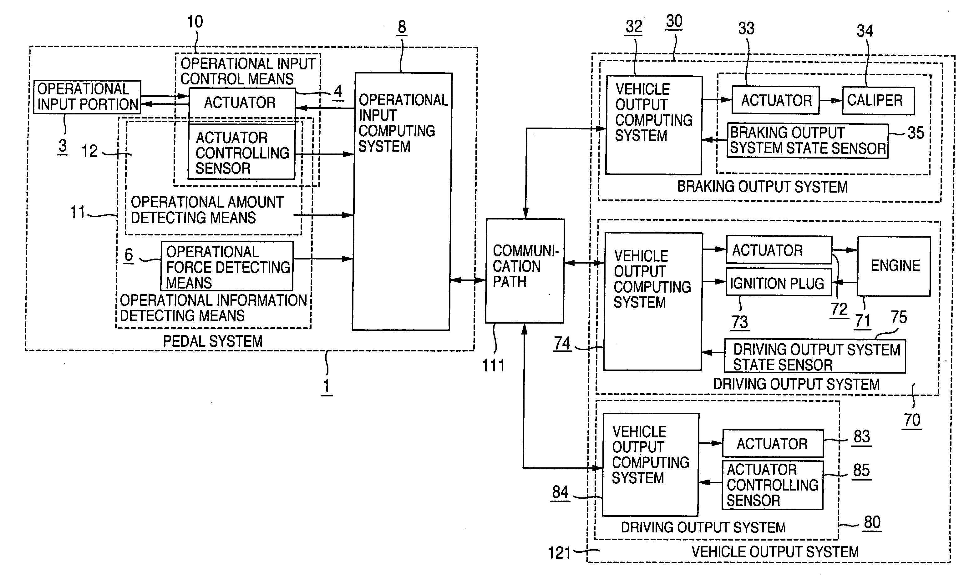
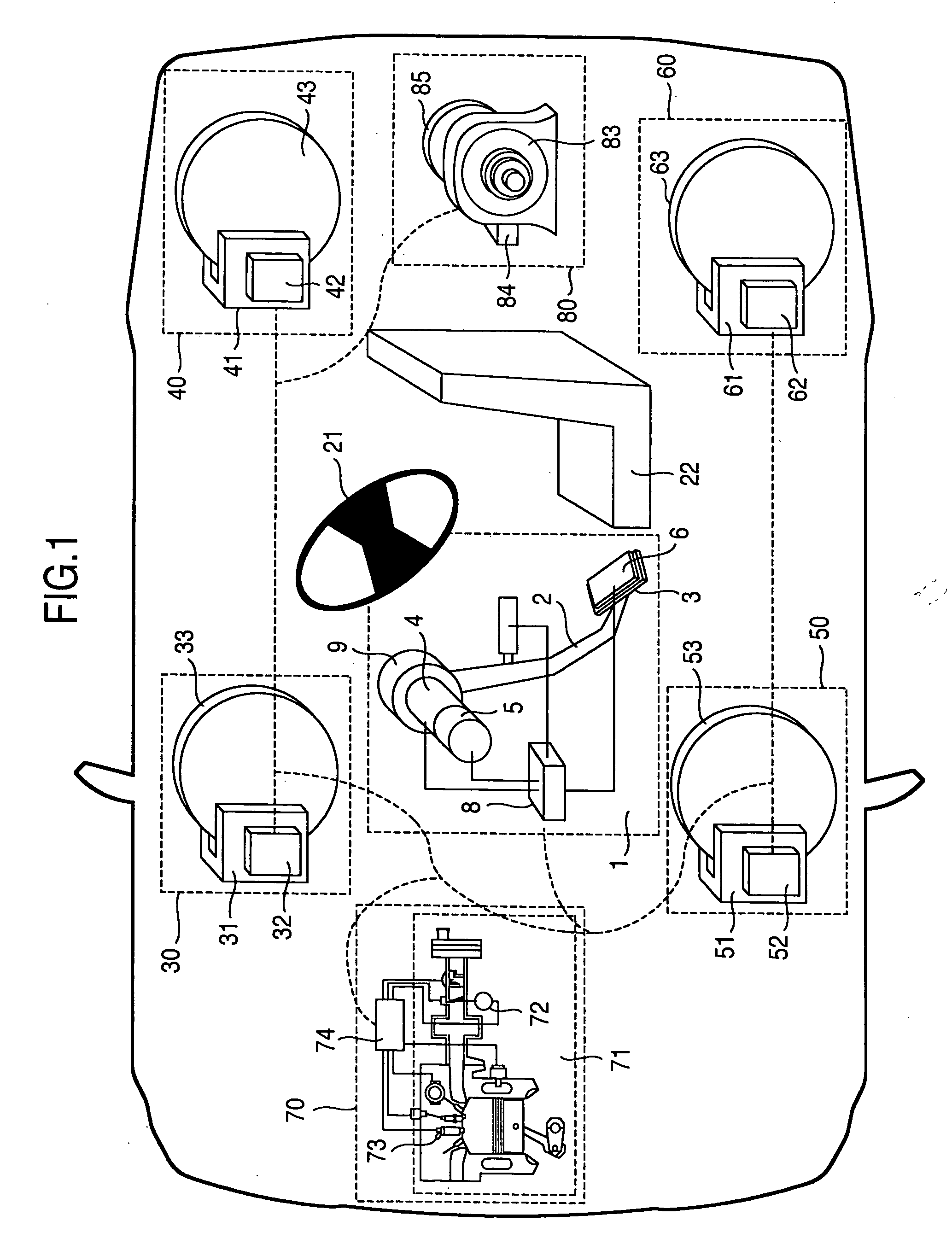
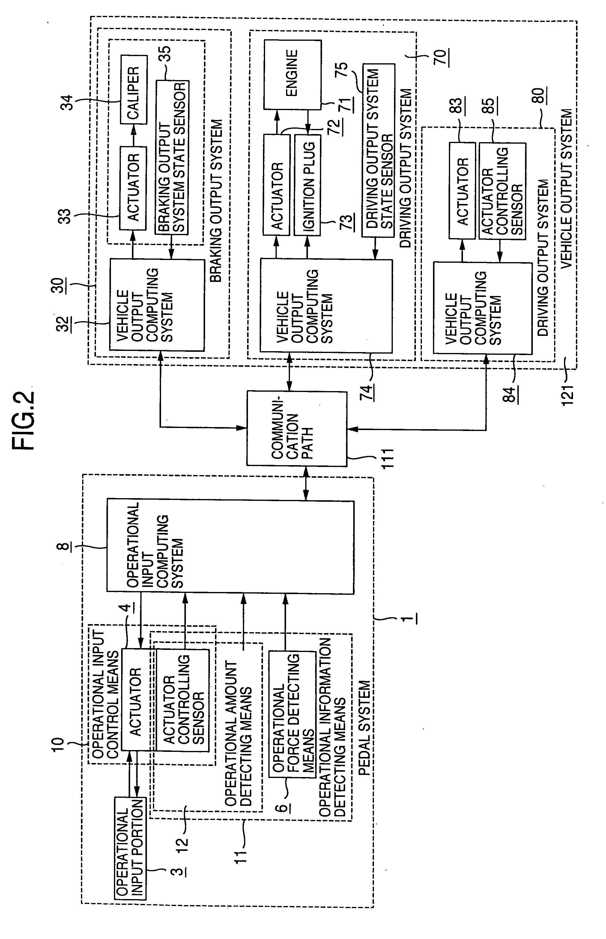
[0042]FIG. 1 is a schematic view of a system structuring the present invention. Further, FIG. 2 is a block diagram of the system structuring the present invention.

[0043] Reference numeral 1 denotes a pedal system which a driver operates for driving a vehicle. The pedal system 1 changes a pedal position and a pedal speed within a fixed range, for example, on the basis of a pedal effort generated by the driver stepping down. Further, the pedal system 1 carries on a curvilinear motion or a linear motion which is constrained in a fixed range with respect to the pedal effort.

[0044] In this case, all the input which the driver applies to the pedal system is defined as an operational input. The operational input includes a pedal effort, a pedal position, a pedal velocity and an information whether or not the pedal is stepped down.

[0045] In the pedal system 1, the pedal position is changed in correspondence to the pedal effort. Further, the pedal reaction force is generated ...

Example

Embodiment 2

[0211]FIG. 26 is a schematic view of a system constituting an embodiment 2. Further, FIG. 27 is a block diagram of a system constituting the present embodiment. It is possible to similarly apply the matters relating to the pedal reaction force in the present invention described in the embodiment 1 to a structure shown in FIG. 26.

[0212] Reference numeral 1 denotes a pedal system which the driver operates for driving the vehicle. The pedal system 1 is provided with an actuator 4, and can electrically control the pedal position and the pedal reaction force. Further, the pedal system 1 travels the pedal position in correspondence to the operating force or the pedal effort applied to an operational input portion 3, and generates the pedal reaction force in correspondence to the pedal position. A relation between the pedal position and the pedal reaction force or the pedal effort can be optionally set on the basis of an electrical control.

[0213] Further, reference numerals ...

Example

Embodiment 3

[0217]FIG. 28 is a schematic view of a system constituting an embodiment 3. Further, FIG. 29 is a block diagram of a system constituting the present embodiment. It is possible to similarly apply the matters relating to the pedal reaction force in the present invention described in the embodiment 1 to a structure shown in FIG. 28.

[0218] Reference numeral 1 denotes a pedal system which the driver operates for driving the vehicle. The pedal system 1 is provided with an actuator 4, and can electrically control the pedal position and the pedal reaction force. Further, the pedal system 1 travels the pedal position in correspondence to the operating force or the pedal effort applied to an operational input portion 3, and generates the pedal reaction force in correspondence to the pedal position. A relation between the pedal position and the pedal reaction force or the pedal effort can be optionally set on the basis of an electrical control.

[0219] Further, reference numeral 3...


PUM


Abstract

The invention provides a pedal system in which a preferable characteristic of a pedal and a preferable characteristic of a vehicle motion are achieved by changing a stiffness of the pedal and an outputting way of a vehicle output in accordance with a parameter on the basis of an operational information, a vehicle information and an environmental information, and a vehicle system with the pedal system. Even if the state of the vehicle changes, a gradient of the pedal reaction force or the vehicle output is changed in correspondence to the parameter without changing the pedal reaction force or the vehicle output. Further, the present invention changes a minimum pedal effort necessary for moving the pedal position at a time of stepping down the pedal from a state in which the pedal is not stepped down, or a minimum pedal position or pedal effort necessary for outputting the vehicle output at a time of stepping down the pedal from the state in which the pedal is not stepped down, in correspondence to the parameter.

Description

TECHNICAL FIELD [0001] The present invention relates to a pedal system which can electrically control a pedal position or a pedal reaction force and a vehicle system with the pedal system. BACKGROUND ART [0002] A driving force and a braking force of the vehicle have been conventionally operated by a pedal. A driver feels an inertia force generated by an acceleration and a deceleration of the vehicle together with a reaction force of the pedal, by pedaling. Accordingly, characteristics such as the pedal position, the pedal reaction force, a driving force of the vehicle, the braking force of the vehicle and the like correspond to factors for determining a drive feeling, an easiness for operation, an easiness for fatigue due to the operation and the like. [0003] On the other hand, since the conventional pedal is mechanically coupled to an accelerator wire and a master cylinder, the characteristics of the pedal are uniquely determined by the mechanism. [0004] However, in recent years, a...

Claims


Application Information

Patent Timeline
IPC IPC(8): G06F17/00B60K26/02B60T7/06
CPCB60K26/021B60T7/042B60W50/08G05G5/03G05G1/38G05G1/405B60W50/16
Inventor UENO, KENTAROSASAKI, MITSUHIDE
Owner HITACHI LTD
Why Eureka
Try Eureka