Navigation system

a navigation system and navigation system technology, applied in navigation instruments, surveying and navigation, instruments, etc., can solve problems such as discrepancies or inconsistencies between the representation of the road and the guidance line, and achieve the effect of reducing the processing load of the navigation system

Inactive Publication Date: 2006-10-05
DENSO CORP
View PDF7 Cites 37 Cited by
  • Summary
  • Abstract
  • Description
  • Claims
  • Application Information

AI Technical Summary

Benefits of technology

[0008] The navigation system of the present invention divides the map data into a mesh of small areas, and processes one of those areas at a time. That is, the nodes such as the...

Problems solved by technology

However, data being used to represent the guidance line only includes positional (two-dimensional) informa...

Method used


Image

  • Navigation system
  • Navigation system
  • Navigation system

Examples


modification 1

[0052] (Modification 1)

[0053]FIG. 4C shows a guidance line drawn at the highest point (Ph) of the ground in the route in the cross-sectional view of the route. However, the guidance line may be drawn by connecting the start point (the current position), the highest point (Ph) and the destination as shown in FIG. 4D. In this manner, the guidance line on a hilly ground in the three-dimensional map becomes less “detached” from the surface of the ground (i.e., the road).

modification 2

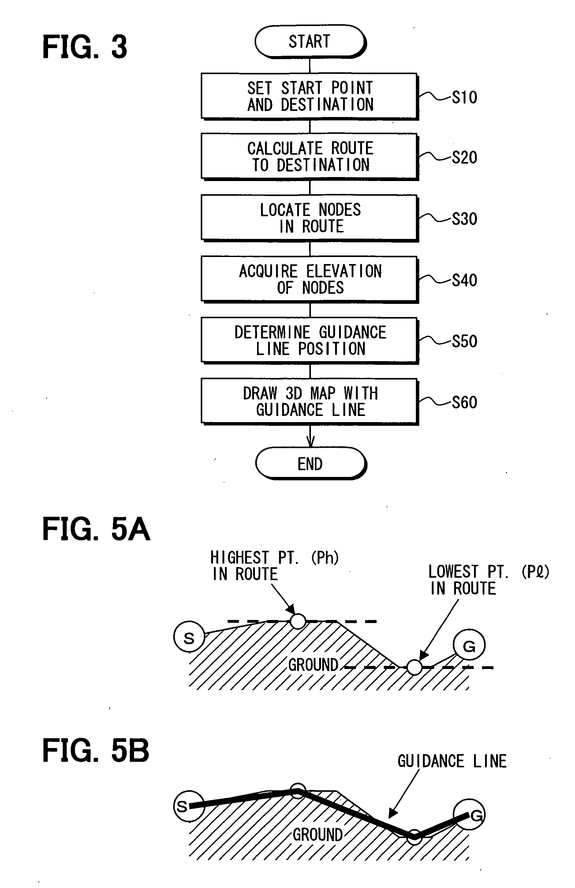
[0054] (Modification 2)

[0055] The guidance line may be drawn as the lines connecting the start point (the current position), the highest point (Ph) of the ground in the route, a lowest point (Pl) of the ground in the route, and the destination after locating those points as shown in FIGS. 5A and 5B. In this manner, the guidance line in the three-dimensional map becomes less detached or less sub-merging on the surface of the ground(i.e., the road).

modification 3

[0056] (Modification 3)

[0057] The guidance line may be drawn as the lines connecting additional points located between the highest / lowest points and the start / end points in the route. That is, as shown in FIGS. 6A and 6B, an additional point may be located as a halfway point between the highest and lowest points (Ph, Pl) in the route. The location of the halfway point is calculated by using the coordinates (latitudes and longitudes) of the two points. The elevation of the drawing position of the guidance line at the halfway point is calculated and determined based on the location coordinates of the halfway point. In this manner, the guidance line in the three-dimensional map is more suitably drawn on the surface of the ground (i.e., the road) as shown in FIG. 6C.

[0058] The divisions between the highest / lowest (Ph, Pl) and other points may be further increased in number for drawing the guidance line more fittingly on the ground as shown in FIG. 6D. The guidance line may also be draw...


PUM


Abstract

A map display system having map data of three dimensions for displaying a three-dimensional map together with a representation of a vector map data includes an elevation acquisition means for acquiring an elevation of a route between a start point to an end point in said three-dimensional map, a position determination means for determining a position of a guidance line in said three-dimensional map based on the elevation of the route, and a map drawing means for drawing said three-dimensional map with the guidance line by using the position of the guidance line. The guidance line is represented along the route in said three-dimensional map by using the vector map data.

Description

CROSS REFERENCE TO RELATED APPLICATION [0001] This application is based on and claims the benefit of priority of Japanese Patent Application No. 2004-372258 filed on Dec. 22, 2004, the disclosure of which is incorporated herein by reference. FIELD OF THE INVENTION [0002] The present invention generally relates to a navigation system. BACKGROUND OF THE INVENTION [0003] A map display device is conventionally used to display a map including a building and a road represented in three-dimensional manner as disclosed in Japanese patent documents JP-A-H10-89990 and JP-A-2001-27535. [0004] For example, a guidance line is displayed for navigational purpose in the three-dimensional map in order to distinguishably represent a route to a destination. In this case, data being used to represent the three-dimensional map includes elevation information, that is, ups and downs of the road or the like, for realistic representation. However, data being used to represent the guidance line only includes...

Claims


Application Information

Patent Timeline
IPC IPC(8): G01C21/32
CPCG01C21/3635
Inventor WATANABE, YOSHINORIFUKUMOTO, MOTOHIRO
Owner DENSO CORP
Why Eureka
Try Eureka