Two-piece filter bag

a filter bag and two-piece technology, applied in the field of filter bags and cages, can solve the problems of difficult to maintain the correct alignment of the bag and the cage, difficult to precisely navigate, and problems such as problems that can occur

Inactive Publication Date: 2006-10-12
ALBANY INT CORP
View PDF17 Cites 4 Cited by
  • Summary
  • Abstract
  • Description
  • Claims
  • Application Information

AI Technical Summary

Benefits of technology

[0012] It is therefore an object of the invention to provide for a multipiece filter bag and cage assembly that will maintain proper bag and cage alignment during installation.

Problems solved by technology

However, the size and weight of the large rigid single construction cage make it difficult to precisely navigate—especially the first half—through the cell plate orifice.
Problems can occur while the filter bag is being inserted.
At this step, it is often difficult to maintain the correct alignment of bag and cage as the cage is being installed.
Typically this difficulty increases with the length of the bag and cage.
Misalignment between the filter bag and cage damages the filter bags.
For example, when the cage is incorrectly seated in the base of the bag the lower end of the bag can be subject to holes, tears, and abrasions.
Similarly, misalignment can cause unnecessary stress throughout the filter media, which can also lead to holes, tears, and abrasions.
At best this wear and tear on the filter bag shortens its normal operating lifespan.
At worst, for example in the event of a tear, it renders the bag immediately inoperable.
Filter bag and cage alignment remains a problem despite recent improvements in filter arrangements.
Unlike the filter media, such a large rigidly constructed cage could not be folded for transportation or storage.
For dust collector systems with low cell plate headspace, where the cage is inserted section by section, the problem of bag and cage alignment is exacerbated.
As with the single structure cage configuration, this difficulty increases with the length of the bag and cage.

Method used


Image

  • Two-piece filter bag
  • Two-piece filter bag
  • Two-piece filter bag

Examples


Embodiment Construction

[0030] Turning now more particularly to the drawings, the filter bag assembly of the present invention has widespread industrial application. FIG. 1 shows a typical application of a filter bag and cage system. Containment vessel 10 includes a lower lateral input aperture 1 into which a particulate stream to be filtered is input. A plurality of filter bag cages 2, 3, 4, 5 supports a corresponding plurality of filters bags 6, 7, 8, 9 so as to expose the filter bags 6-9 to the particulate gas stream and to prevent the filter bags 6-9 from collapsing. The particulate gas stream is filtered as it passes through the filters 6-9. The filtered gas stream thereafter passes out through upper lateral output aperture 11. The filtered particulates accumulate on the filter bags 6-9 and eventually drop to the inverted conical lower portion 12 of containment vessel 10 to be removed by sweeping device 13.

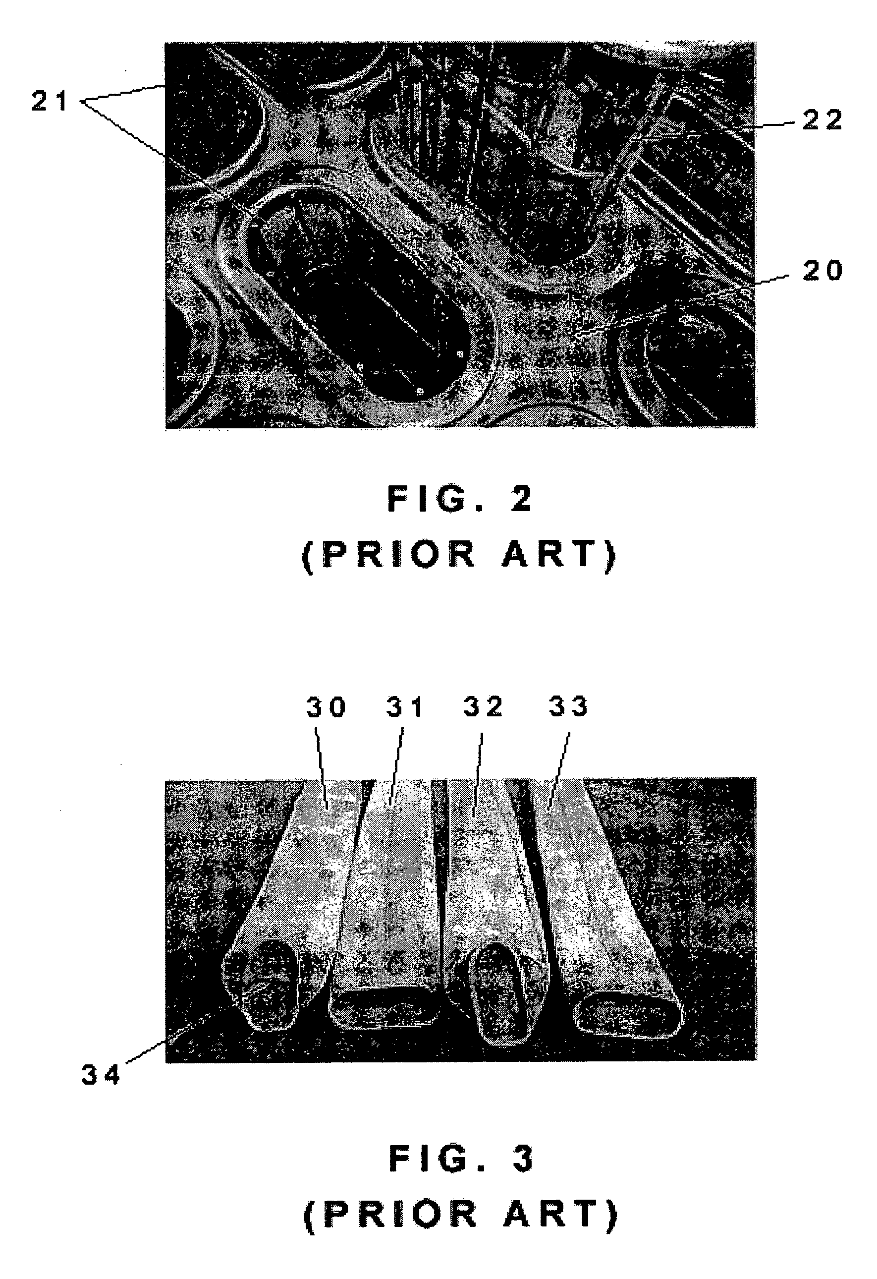
[0031]FIG. 2 shows an image of known prior art bag cages having an oblong circumference. The ce...


PUM

PropertyMeasurementUnit
lengthaaaaaaaaaa
shapeaaaaaaaaaa
surface areaaaaaaaaaaa

Abstract

A bag and cage filter assembly for filtering particulates out of a stream of gas, which includes a plurality of elongated filter bag sections with a support cage, The bag sections are fastened together, as may be the cage sections.

Description

FIELD OF THE INVENTION [0001] The present invention relates to a filter bag and cage, in particular a two-piece filter bag that allows for maintaining correct bag-to-cage alignment during installation. BACKGROUND OF THE INVENTION [0002] Filters have wide commercial applications and utility in industries including but not limited to alumina, wood, plastic, steel, paper, glass, cement, chemical processing, waste incineration, power generation, smelting and mining. Filters generally involve the use of a filter media. Filter media can include but is not limited to: needled felt, nonwoven material, woven material, knitted fabric, fiberglass and / or metal fabrics, foam coated fabrics or a laminate of at least two of these structures. The filter media may or may not require a supporting structure. For example, filters made from a woven or nonwoven textile material for particulate filtration from gas streams are often supported by way of cages made from metal or other suitable material. In o...

Claims


Application Information

Patent Timeline
Patent Type & Authority Applications(United States)
IPC IPC(8): B01D46/02
CPCB01D2265/02B01D46/02
Inventor NEATE, MICHAELCURRELL, BRAD
Owner ALBANY INT CORP
Why Eureka
Try Eureka