Trans-thermoelectric device

a thermoelectric device and trans-thermoelectric technology, applied in the field of thermoelectric devices, can solve the problems of low efficiency of commercial thermoelectric devices, complicated manufacturing process, and low thermoelectric device cost efficiency, and achieve the effects of reducing the complexity of module assembly, improving thermoelectric material properties, and improving efficiency

Inactive Publication Date: 2006-10-12
LAIRD THERMAL SYST INC
View PDF25 Cites 39 Cited by
  • Summary
  • Abstract
  • Description
  • Claims
  • Application Information

AI Technical Summary

Benefits of technology

[0009] A further object of the present invention is to provide a device fabrication process which reduced the complexity of assembly of modules.
[0010] Still, a further object of the present invention is to provide higher efficiency thermoelectric devices by utilizing in the thermoelectric devices the specific n- or p-type thermoelectric material that has the better thermoelectric material properties.

Problems solved by technology

Current designs of commercially available thermoelectric devices have efficiencies too low to warrant widespread cooling application.
However, the utilization of different n and p-type materials adds complications to the manufacturing process and frequently costs efficiency of the fabricated thermoelectric device, as the thermoelectric performance of one of the n and p-type materials is typically lower the thermoelectric performance of the other of the opposite type.

Method used


Image

  • Trans-thermoelectric device
  • Trans-thermoelectric device
  • Trans-thermoelectric device

Examples


Embodiment Construction

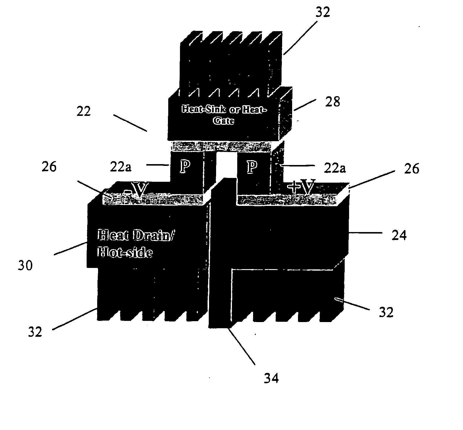
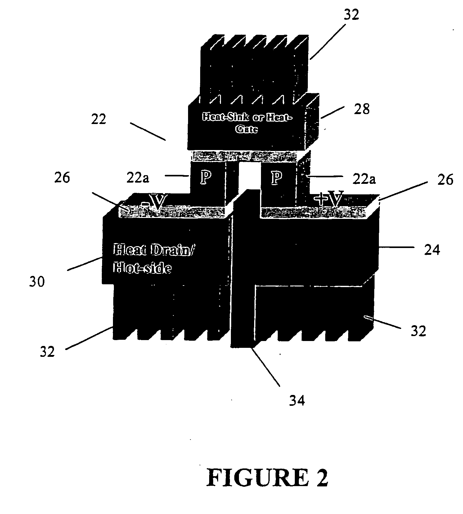
[0022] Referring now to the drawings, wherein like reference numerals designate identical, or corresponding parts throughout the several views, and more particularly to FIG. 2, FIG. 2 depicts a trans-thermoelectric device 20 of the present invention. The trans-thermoelectric device 20 includes a three-thermal-terminal (T3) p-p couple element 22 shown in FIG. 2 as having a configuration for cooling a heat source 24. The trans-thermoelectric device 20, while shown having a p-p couple, could instead be an n-n couple element. In either case, the unipolar couple element 22 has two legs 22a of a same electrical conductivity type. As shown in FIG. 2, electrical terminals 26 connected to respective ends of the two legs 22a on one side of the unipolar couple element 22. The heat source 24 constitutes a first-temperature stage connected to one of the legs 22a. A heat sink / gate 28 constitutes a second-temperature stage and is connected to a side of the unipolar couple element 22 opposite the e...


PUM


Abstract

A thermoelectric device having at least one unipolar couple element (22) including two legs (22a) of a same electrical conductivity type. A first-temperature stage (24) is connected to one of the two legs. A second-temperature stage (28) is connected across the legs of the at least one unipolar couple element. A third-temperature stage (30) is connected to the other of the two legs. Methods for cooling an object and for thermoelectric power conversion utilize the at least one unipolar couple element to respectively cool an object and produce electrical power.

Description

FIELD OF THE INVENTION [0001] This invention relates to the field of thermoelectric devices and methods of manufacturing such devices. BACKGROUND OF THE INVENTION [0002] A thermoelectric device is capable of generating electricity if two ends of the thermoelectric device are held at different temperatures. When two dissimilar metals (conductors) or semiconductors having different Seebeck potential or Fermi energy levels are in contact at each end, a voltage is obtained if the ends are at different temperatures (i.e., the Seebeck effect). Conversely, an applied electrical current can induce a temperature differential between the two ends due to the Peltier effect. The Peltier effect causes absorption or liberation of heat when current flows across the junction of two dissimilar materials. As electrons flow from a p-type semiconductor to an n-type semiconductor an energy gap or “hurdle” is traversed. Thermal energy is absorbed as electrons overcome this energy hurdle, and this junctio...

Claims


Application Information

Patent Timeline
Patent Type & Authority Applications(United States)
IPC IPC(8): H01L35/30H01L35/16H01L35/32
CPCB82Y10/00H01L35/16H01L35/30H01L35/32H01L2924/0002H01L2924/00H10N10/852H10N10/17H10N10/13H10N10/81
Inventor VENKATASUBRAMANIAN, RAMACOONLEY, KIPDSIIVOLA, EDWARDPPUCHAN, MICHAELALLEY, RANDALLGADDEPALLI, PRATIMAO'QUINN, BROOKSCCOLPITTS, THOMASNAPIER, MARY
Owner LAIRD THERMAL SYST INC
Why Eureka
Try Eureka