Sample milling/observing apparatus and method of observing sample

a technology of sample milling and observing apparatus, which is applied in the direction of material analysis using wave/particle radiation, instruments, nuclear engineering, etc., can solve the problems of cumbersome observation of the change of section, electron beam, and inability of the electronic microscope to cope with the case, so as to achieve simple and easy observation, simple and easy adjustment

Inactive Publication Date: 2006-10-12
RENESAS ELECTRONICS CORP
View PDF3 Cites 26 Cited by
  • Summary
  • Abstract
  • Description
  • Claims
  • Application Information

AI Technical Summary

Benefits of technology

[0013] In the method of observing a sample, when the observed section is formed by irradiation of the ion beam obtained by the ion gun, the relationship between the observed section and the focal point of the electron beam is adjusted on the basis of an amount of cut of the sample. In this manner, when the focal point of the electron beam is adjusted to the observed section before irradiation of the ion beam, the focal point of the electron beam can be simply and easily adjusted to a new observed section even after the irradiation.
[0014] In the sample milling / observing apparatus according to the present invention, since a focal point of the electron beam is automatically adjusted to the observed section in accordance with cutting of the sample by the ion beam, adjustment of the focal point of the electron beam need not be manually performed each time the observed section is updated, and a change of the cross section of the sample can be simply and easily observed.
[0015] In the method of observing a sample according to the present invention, since a focal point of the electron beam is adjusted to the observed section on the basis of an amount of cut when the sample is cut by the ion beam, adjustment of the focal point of the electron beam can be appropriately performed when the observed section is updated, and a change of the section of the sample is advantageously observed.

Problems solved by technology

For this reason, the electronic microscopes cannot cope with a case in which the observed section of the sample is cut to change the depth thereof.
In this manner, each time the observed section is updated by the ion beam, the electron beam must be focused and make observation of the change of the section cumbersome.

Method used


Image

  • Sample milling/observing apparatus and method of observing sample
  • Sample milling/observing apparatus and method of observing sample
  • Sample milling/observing apparatus and method of observing sample

Examples


first embodiment

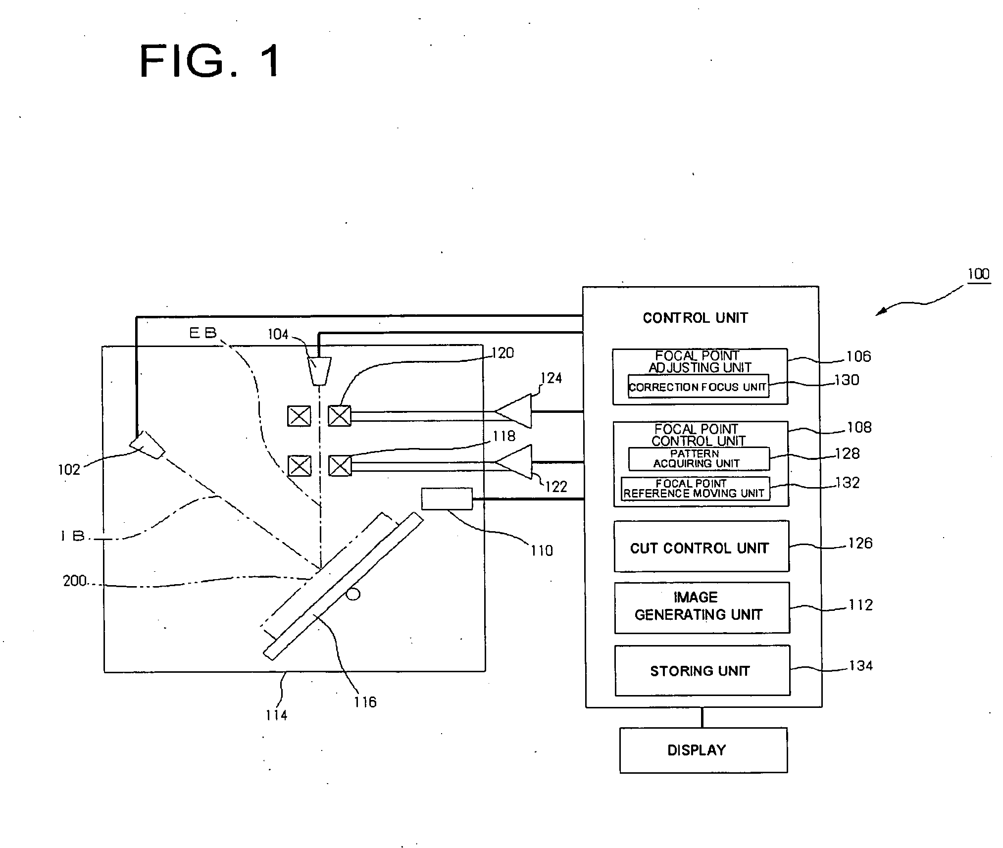
[0029]FIG. 1 is a schematic structural diagram of a sample milling / observing apparatus showing the present invention.

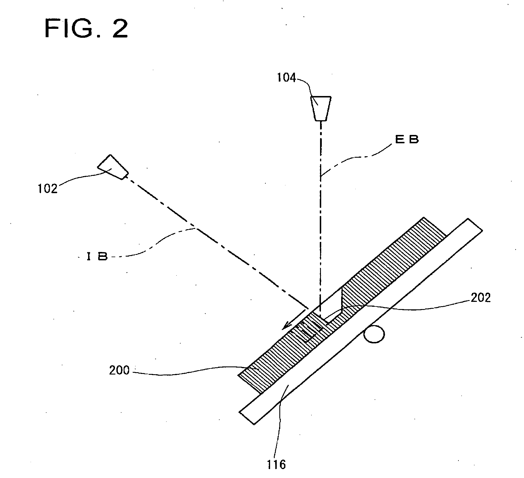
[0030] As shown in FIG. 1, a sample milling / observing apparatus 100 includes an ion gun 102 which irradiates an ion beam IB onto a sample 200 to form an observed section 202 (see FIG. 2), an electron gun 104 which irradiates an electron beam EB onto the observed section 202 formed by the ion gun 102, a focal point adjusting unit 106 which adjusts a relationship between the observed section 202 and a focal point of the electron beam EB, and a focal point control unit 108 which controls the focal point adjusting unit 106 on the basis of an amount of cut of the sample 200 obtained by irradiation of the ion beam IB of the ion gun 102.

[0031] The sample milling / observing apparatus 100 includes a detecting unit 110 which detects a signal generated by irradiation of the electron beam EB onto the observed section 202 and an image generating unit 112 which generates an image o...

second embodiment

[0063]FIG. 8 is a typical schematic diagram of a sample milling / observing apparatus showing the present invention.

[0064] As shown in FIG. 8, a sample milling / observing apparatus 300 includes an ion gun 102 which irradiates an ion beam IB onto a sample 200 to form an observed section 202, an electron gun 104 which irradiates an electron beam EB onto the observed section 202 formed by the ion gun 102, a focal point adjusting unit 306 which can adjust a relative position between the observed section 202 and a focal point of the electron beam EB, and a focal point control unit 308 which controls the focal point adjusting unit 306 on the basis of an amount of cut of the sample 200 obtained by irradiation of the ion beam IB of the ion gun 102 to adjust the relative position.

[0065] The sample milling / observing apparatus 300 includes a detecting unit 110 which detects a signal generated by irradiation of the electron beam EB onto the observed section 202 and an image generating unit 112 wh...


PUM


Abstract

When a sample is cut to update an observed section, an electron beam is focused on the observed section. An apparatus of the invention includes an ion gun 102 which irradiates an ion beam onto a sample 200 to form an observed section 202, an electron gun 104 which irradiates an electron beam EB onto the observed section 202 formed by the ion gun 102, a focal point adjusting unit 106 which adjusts a relationship between the observed section 202 and a focal point of the electron beam EB, and a focal point control unit 108 which controls the focal point adjusting unit 106 on the basis of an amount of cut of the sample 200 obtained by irradiation of the ion beam IB obtained by the ion gun 102.

Description

[0001] This application is based on Japanese Patent application NO. 2005-111441, the content of which is incorporated hereinto by reference. BACKGROUND [0002] 1. Technical Field [0003] The present invention relates to a sample milling / observing apparatus including an ion gun which irradiates an ion beam on a sample to form a cross-section to be observed (hereinafter, to be referred to as observed section) and a method of observing a sample using the milling / observing apparatus for the sample. [0004] 2. Related Art [0005] As an electronic microscope which observes a sample, a scanning electronic microscope (SEM) is known. When a sample is observed by the electronic microscope of this type, in general, the sample is placed on a predetermined stage, and an electron beam is focused on an observed surface of the sample in accordance with a tilt state of the observed surface. The electron beam is focused by changing a magnetic field of an object lens. [0006] In this case, the stage is arr...

Claims


Application Information

Patent Timeline
Patent Type & Authority Applications(United States)
IPC IPC(8): H01J37/08
CPCH01J37/21H01J2237/28H01J37/3056H01J37/3005
Inventor FUJII, AKIKO
Owner RENESAS ELECTRONICS CORP
Why Eureka
Try Eureka