Closed enclosure electric machine

a closed enclosure and electric machine technology, applied in the direction of windings, magnetic circuit rotating parts, magnetic circuit shapes/forms/constructions, etc., can solve the problem that conventional electric machines containing a longer rotor and a smaller diameter are vulnerable to thermal failur

Inactive Publication Date: 2006-10-12
YANG TAI HER
View PDF3 Cites 16 Cited by
  • Summary
  • Abstract
  • Description
  • Claims
  • Application Information

AI Technical Summary

Problems solved by technology

Conventional electric machine in a structural type containing a longer rotor in smaller diameter is vulnerable to thermal failure by accumulation of heat in the mid section due to poor air circulation.

Method used


Image

  • Closed enclosure electric machine
  • Closed enclosure electric machine
  • Closed enclosure electric machine

Examples


Embodiment Construction

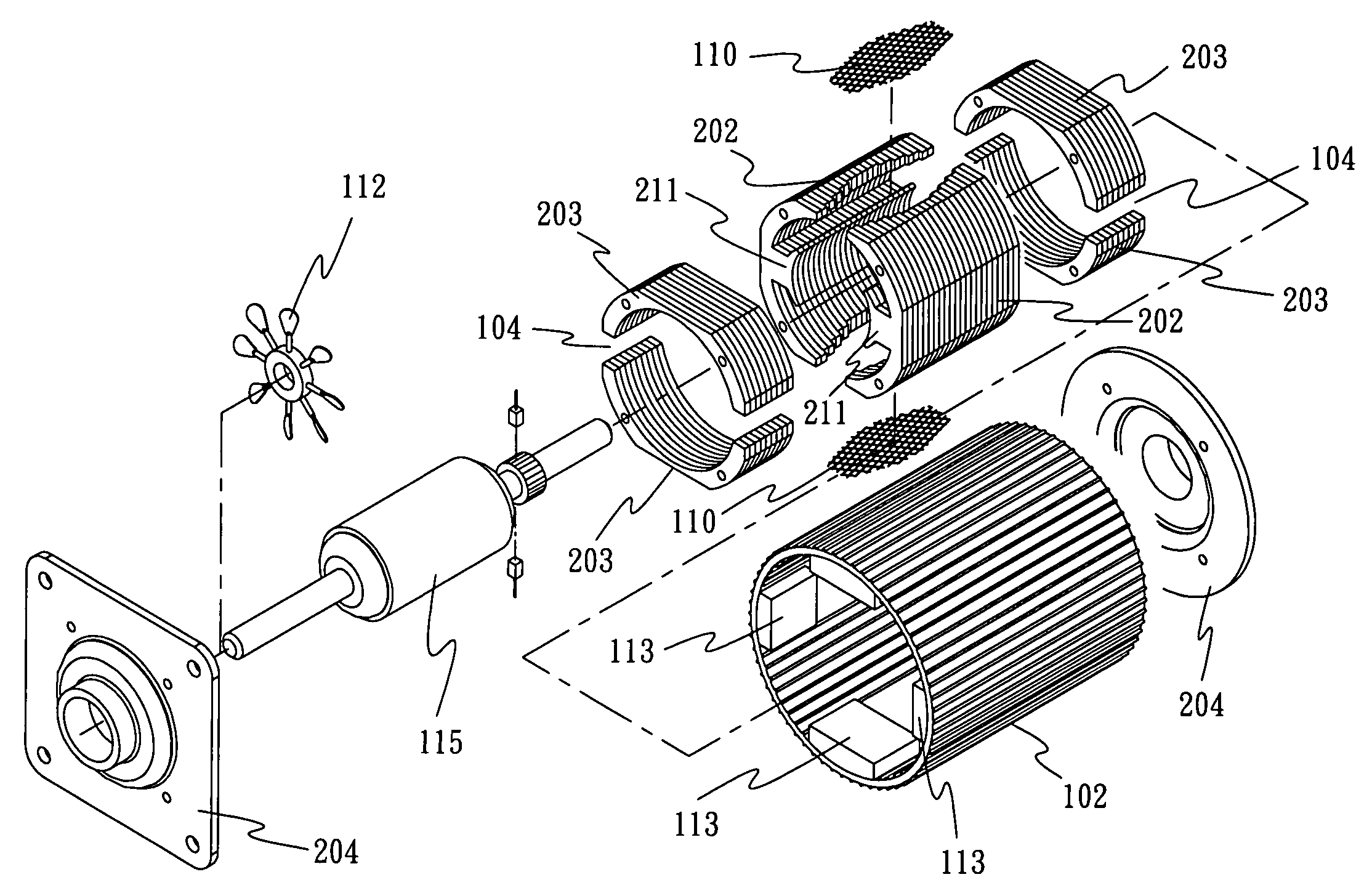
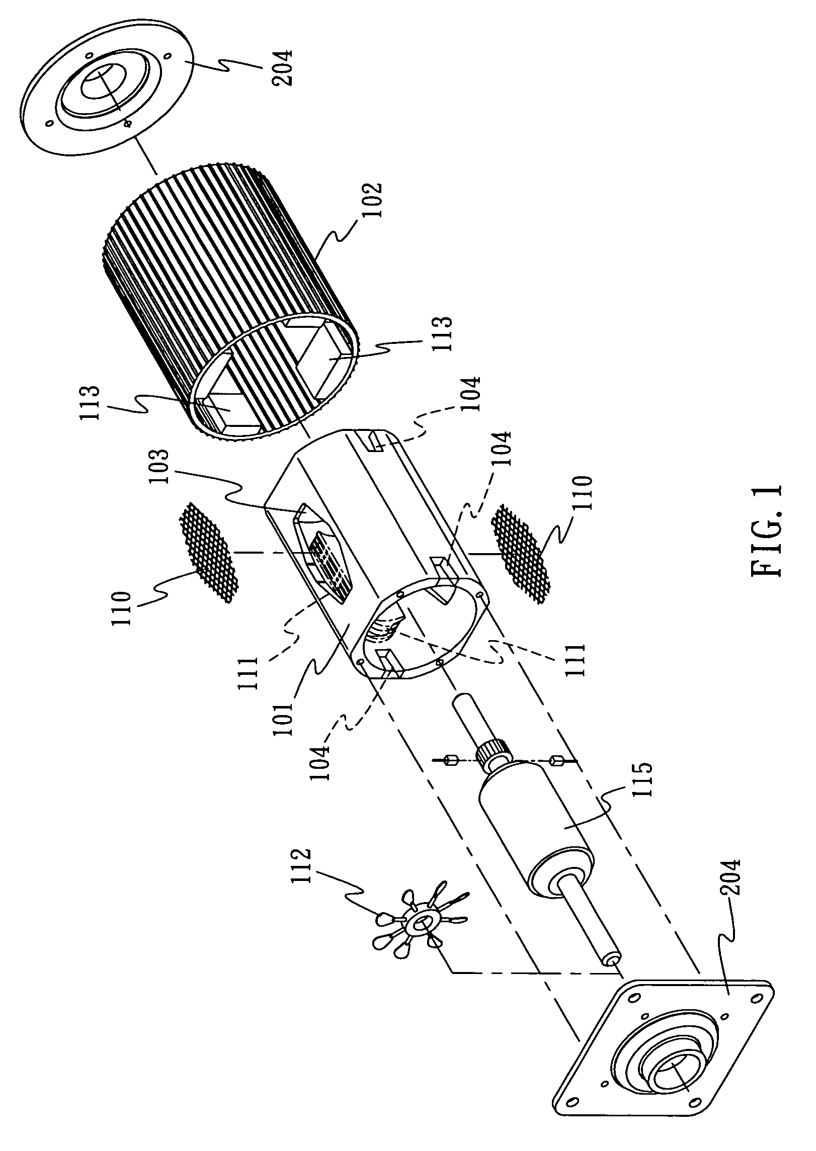
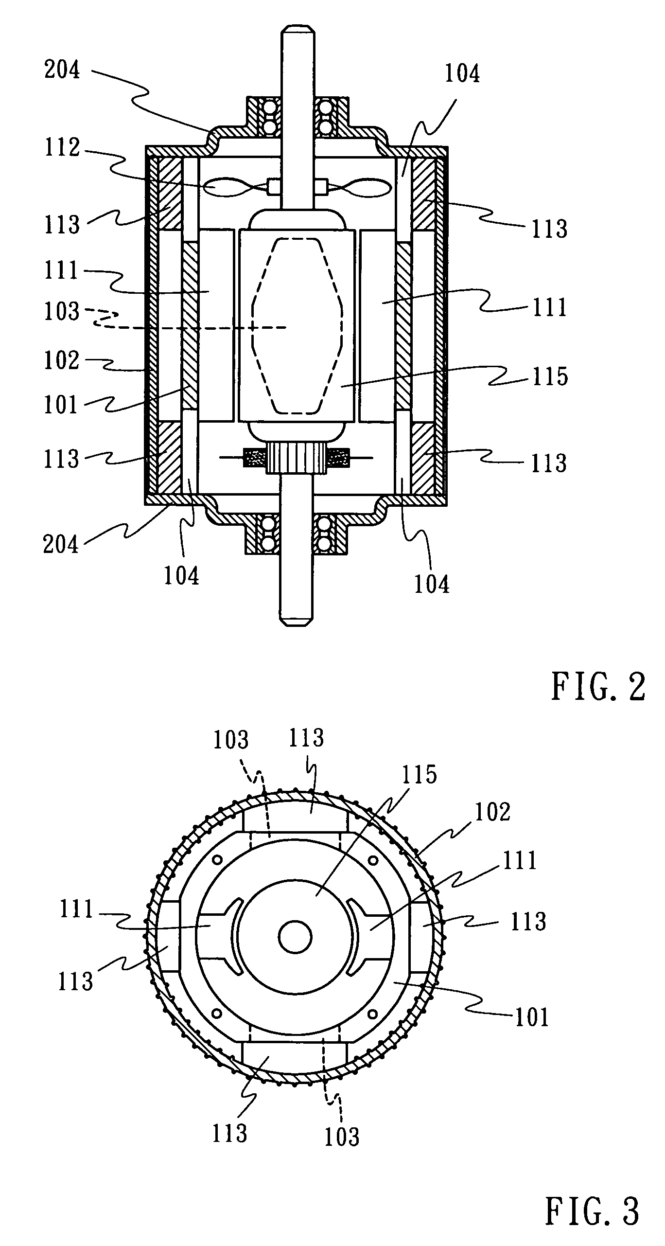
[0029] The present invention is to provide an AC or DC internal or external rotation rotary electric machine or linear machine provided with magnetic pole structure. One or a plurality radius or circumambient air chamber and radius or slotted through hole disposed in the middle between abutted magnetic poles, and optionally one or a plurality of notch, through hole, or slotted through hole formed respectively at both ends at the proximate end casing along a neutral line of magnetic pole to constitute an air current passage. A circular radiation casing connecting through the internal of the electric machine via the notch, through hole or slotted hole is provided externally to the structure of the magnetic path; a space is defined between the circular heat sink casing and the outer casing of the magnetic path to admit airflow. The circular heat sink and closed enclosures at both ends of the electric machine constitute a closed enclosure electric machine to allow circulation of airflow...


PUM


Abstract

An AC or DC, internal or external rotation rotary or linear electric machine with magnetic poles; one or a plurality radius or circumambient air chamber and radius or slotted through hole disposed between abutted magnetic poles, and optionally one or a plurality of notch, through hole, or slotted through hole formed respectively at both end casing along a neutral line of magnetic pole to constitute an air current passage; a circular radiation casing connecting through the internal of the electric machine via the notch, through hole or slotted hole being provided externally to the magnetic path; a space being defined between the circular heat sink casing and the outer casing of the magnetic path to admit airflow; the circular heat sink and closed enclosures at both ends constitute a closed enclosure electric machine to allow circulation of airflow inside the electric machine and to be discharged into the ambient through the casing of the circular heat sink.

Description

BACKGROUND OF THE INVENTION [0001] (a) Field of the Invention [0002] The present invention is related to a closed enclosure electric machine adapted with air chamber and radius through hole, and more particularly, to an AC or DC rotary electric machinery of provided with magnetic pole structure, one or a plurality radius or circumambient air chamber and radius or slotted through hole disposed in the middle between abutted magnetic poles, and optionally one or a plurality of notch, through hole, or slotted through hole formed respectively at both ends at the proximate end casing along a neutral line of magnetic pole to constitute an air current passage. A circular radiation casing connecting through the internal of the electric machine via the notch, through hole or slotted hole is provided externally to the structure of the magnetic path; a space is defined between the circular heat sink casing and the outer casing of the magnetic path to admit airflow. The circular heat sink and cl...

Claims


Application Information

Patent Timeline
Patent Type & Authority Applications(United States)
IPC IPC(8): H02K9/00H02K3/24H02K5/00H02K1/00
CPCH02K1/20H02K9/22H02K9/06H02K5/20H02K9/227H02K5/207
Inventor YANG, TAI-HER
Owner YANG TAI HER
Why Eureka
Try Eureka