Multivariable generator and method of using the same

a generator and multi-variable technology, applied in the direction of synchronous generators with multiple outputs, magnetic circuit rotating parts, magnetic circuit shapes/forms/construction, etc., can solve the problems of limiting the output efficiency of electrical generators, reducing the lifespan of electrical generators, and under-efficiency of generator outputs, so as to improve output efficiency, reduce heat generation, and increase the effect of operation li

Inactive Publication Date: 2006-10-12
CAMEL CLUB
View PDF75 Cites 23 Cited by
  • Summary
  • Abstract
  • Description
  • Claims
  • Application Information

AI Technical Summary

Benefits of technology

[0015] Another object of the present invention is to provide a method of using a generator capable of having an increased operational lifespan.
[0016] Another object of the present invention is to provide a method of using a generator capab

Problems solved by technology

In addition, as each alternating magnetic field passes by the core structure, induction of the alternating magnetic fields generates significant amounts of heat within the core structure, thus limiting output efficiency of the electrical generator and reducing the lifespan of the electrical generator.
For example, the significant amounts of heat generated by the electrical generator causes an under-efficiency of the output of the generator.
Moreover, the generation of heat by the electrical generator results in scheduled periodic maintenance, wherein the electrical gen

Method used


Image

  • Multivariable generator and method of using the same
  • Multivariable generator and method of using the same
  • Multivariable generator and method of using the same

Examples


Embodiment Construction

[0043] Reference will now be made in detail to the preferred embodiments of the present invention, examples of which are illustrated in the accompanying drawings.

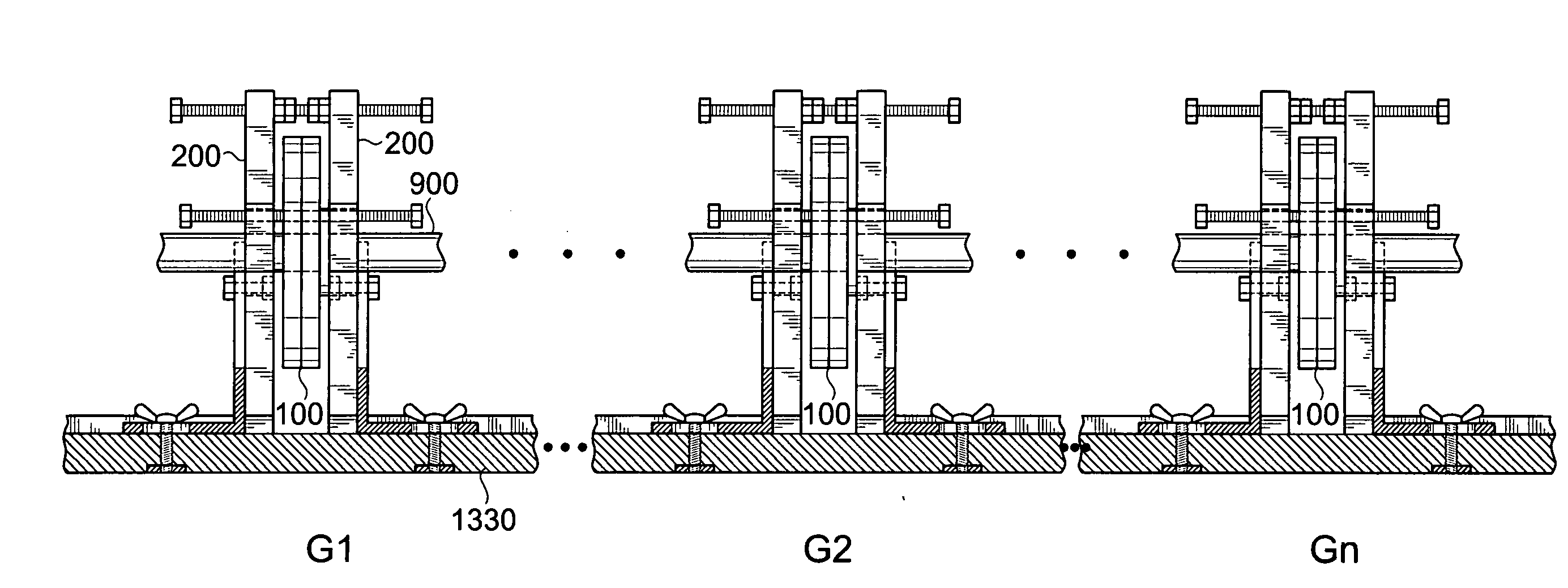
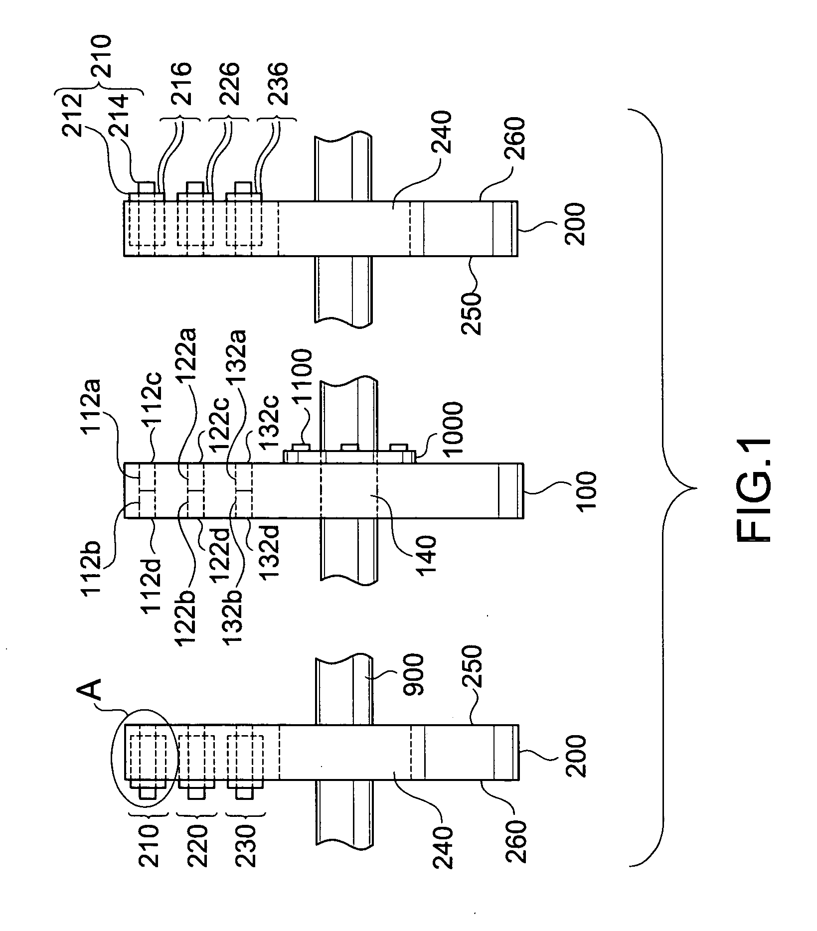
[0044]FIG. 1 is a schematic plan view of an exemplary electrical generator according to the present invention. In FIG. 1, a generator may include a rotor 100 and a pair of stators 200 each disposed on opposing sides of the rotor 100. Each of the rotors 100 and the stators 200 may be made from non-magnetic materials. Alternatively, the generator may include a single rotor 100 and one stator 200 disposed at only one side of the single rotor 100. In addition, the rotor 100 may be mechanically coupled to a rotating shaft 900 using at least one coupling member 1000 having a plurality of fastening members 1100.

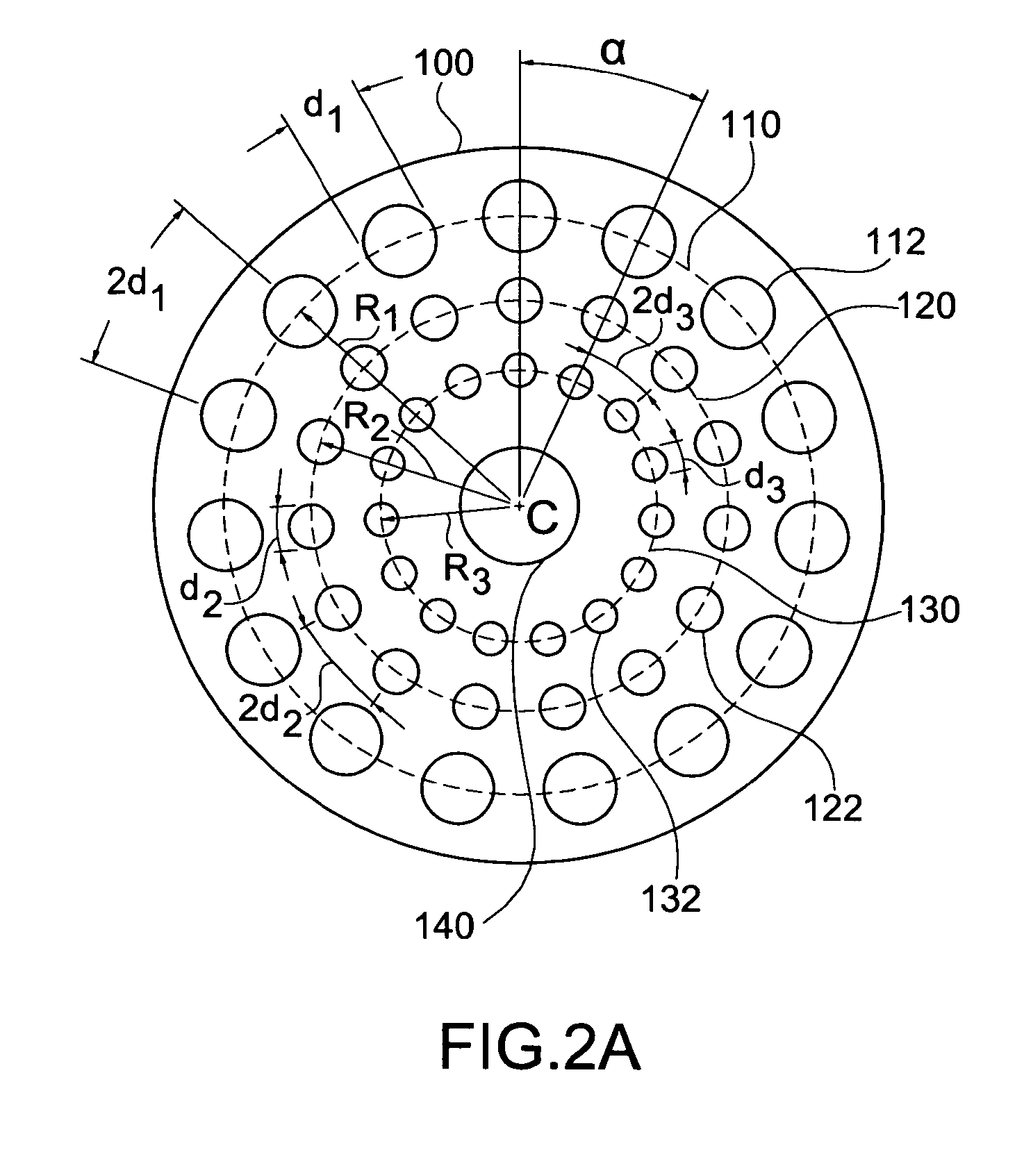
[0045] In FIG. 1, the rotor 100 may include a plurality of magnetic source pairs 112a / 112b, 122a / 122b, and 132a / 132b disposed through a thickness of the rotor 100. Accordingly, each of the magnet source pairs 112a / 112b, 1...


PUM


Abstract

A generator device for generating electrical energy includes a rotor having a first set of even-numbered of magnetic sources distributed along a first radius of the rotor, and a first pair of stators, each having a first set of odd-numbered coil members distributed along a first radius of the stator, the stators disposed adjacent to opposing side portions of the rotor, wherein each coil member includes a core portion having an amorphous structure. In addition, a generator device for generating electrical energy includes interchangeable rotor and stator pairs to provide variable voltage/current/frequency outputs.

Description

[0001] The present application is a Continuation-In-Part of U.S. patent application Ser. No. 10 / 973,825, filed on Oct. 27, 2004, which is hereby incorporated by reference.BACKGROUND OF THE INVENTION [0002] 1. Field of the Invention [0003] The present invention relates to a generator and a method of using a generator, and particularly, to a multivariable generator and method of using a multivariable generator. [0004] 2. Discussion of the Related Art [0005] In general, electrical generators generally include a plurality of magnets arranged to have alternating magnetic field orientations (i.e., North and South) that pass by a plurality of coil windings to generate electrical energy. Specifically, as the magnets become aligned with the core structure of the coil windings, a magnetic field is induced to the core structure thereby generating a current in the coil windings. In addition, as each alternating magnetic field passes by the core structure, induction of the alternating magnetic f...

Claims


Application Information

Patent Timeline
IPC IPC(8): H02K21/12H02K1/22
CPCH02K21/48H02K21/24
Inventor WISE, RICHARD J.
Owner CAMEL CLUB
Why Eureka
Try Eureka