Door lock with RFID key

a door lock and key technology, applied in the field of electronic door locks, can solve the problems of incompatible power required for such a system with current battery life, contact surface or magnetic strip that can become damaged and unusable, and system is not economically feasible or desirable in some applications, and achieves significant power savings

Inactive Publication Date: 2006-10-12
COMPIZED SECURITY SYST
View PDF8 Cites 44 Cited by
  • Summary
  • Abstract
  • Description
  • Claims
  • Application Information

AI Technical Summary

Benefits of technology

[0009] Accordingly, the electronic latch assembly of this invention provides for the use of an electronic lock with significant power savings enabling the use of a stand alone device with commonly available batteries.

Problems solved by technology

Disadvantageously, smart cards and key cards utilize a contact surface or a magnetic strip that can become damaged and unusable for a variety of reasons including exposure to magnetic fields or simply destruction caused by improper or rough handling.
Such systems are not economically feasible or desirable in some applications such as in multi-housing or hotel / motel applications.
Disadvantageously, the power required for such a system is not compatible with current battery life to support a stand alone system.

Method used


Image

  • Door lock with RFID key
  • Door lock with RFID key
  • Door lock with RFID key

Examples


Embodiment Construction

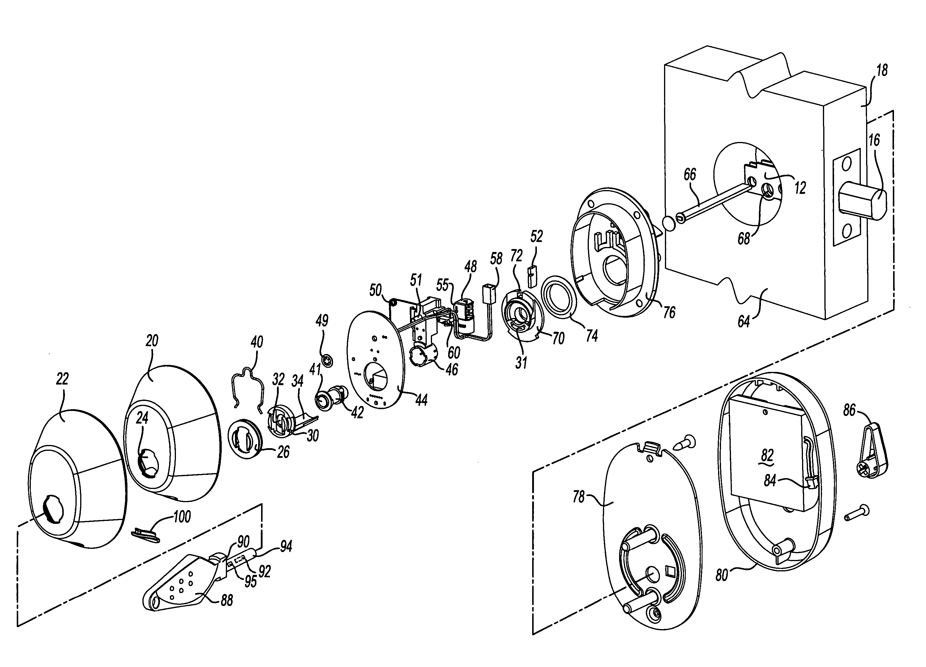
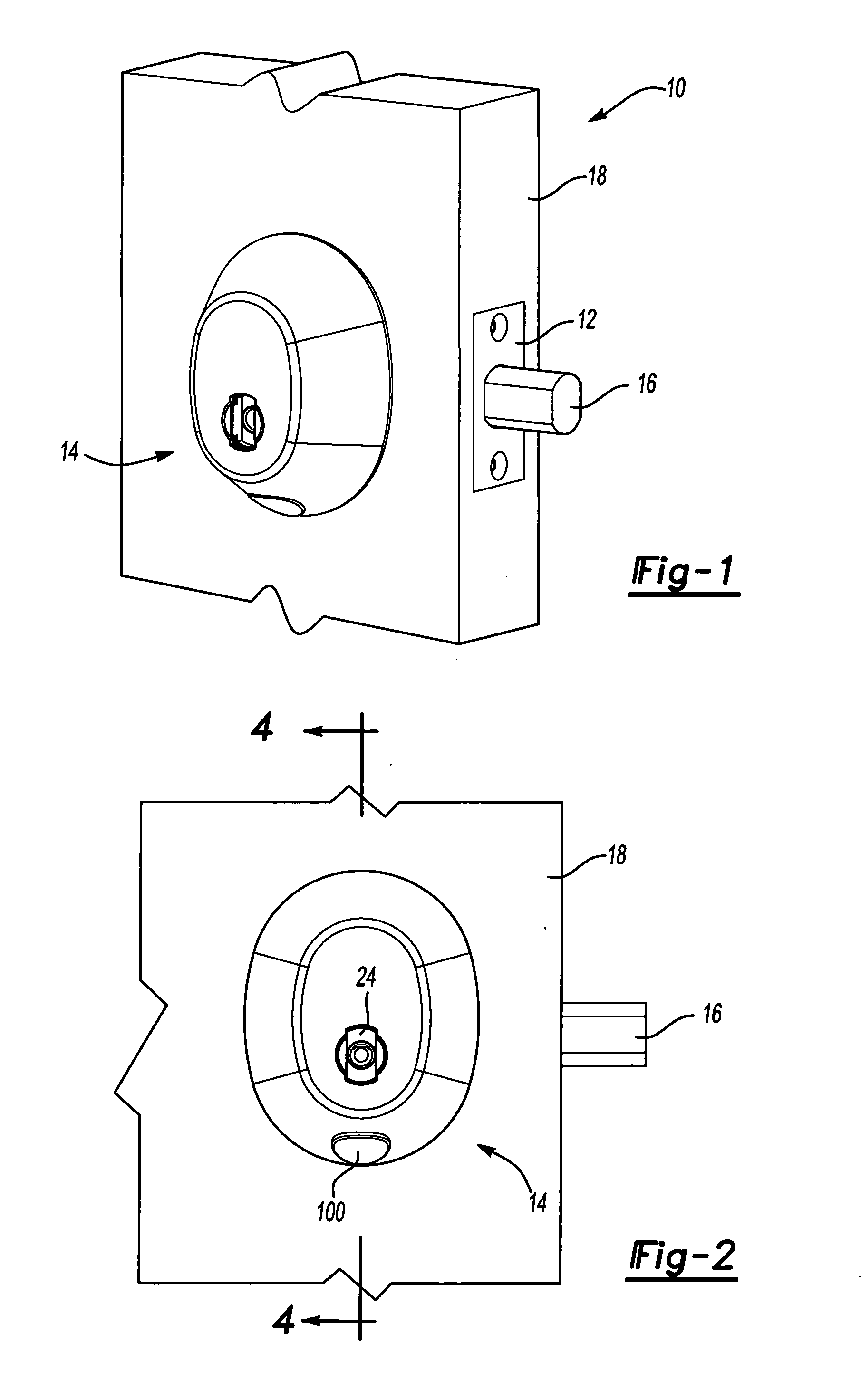
[0017] Referring to FIGS. 1 and 2, a door assembly 10 includes a latch assembly 12 with a main bolt 16. The main bolt 16 extends from the latch assembly 12 to engage a door jam (not shown) thereby preventing the door assembly 10 from being opened. A door 18 also includes an electronic lock assembly 14. The electronic lock assembly 14 corresponds and actuates the latch assembly 12 to extend and retract the main bolt 16. The electronic lock assembly 14 includes an opening 24 for a key 88 (FIG. 3) The electronic lock assembly 14 also includes a removable plug 100 that provides access to an internal electronic connection within the lock assembly 14.

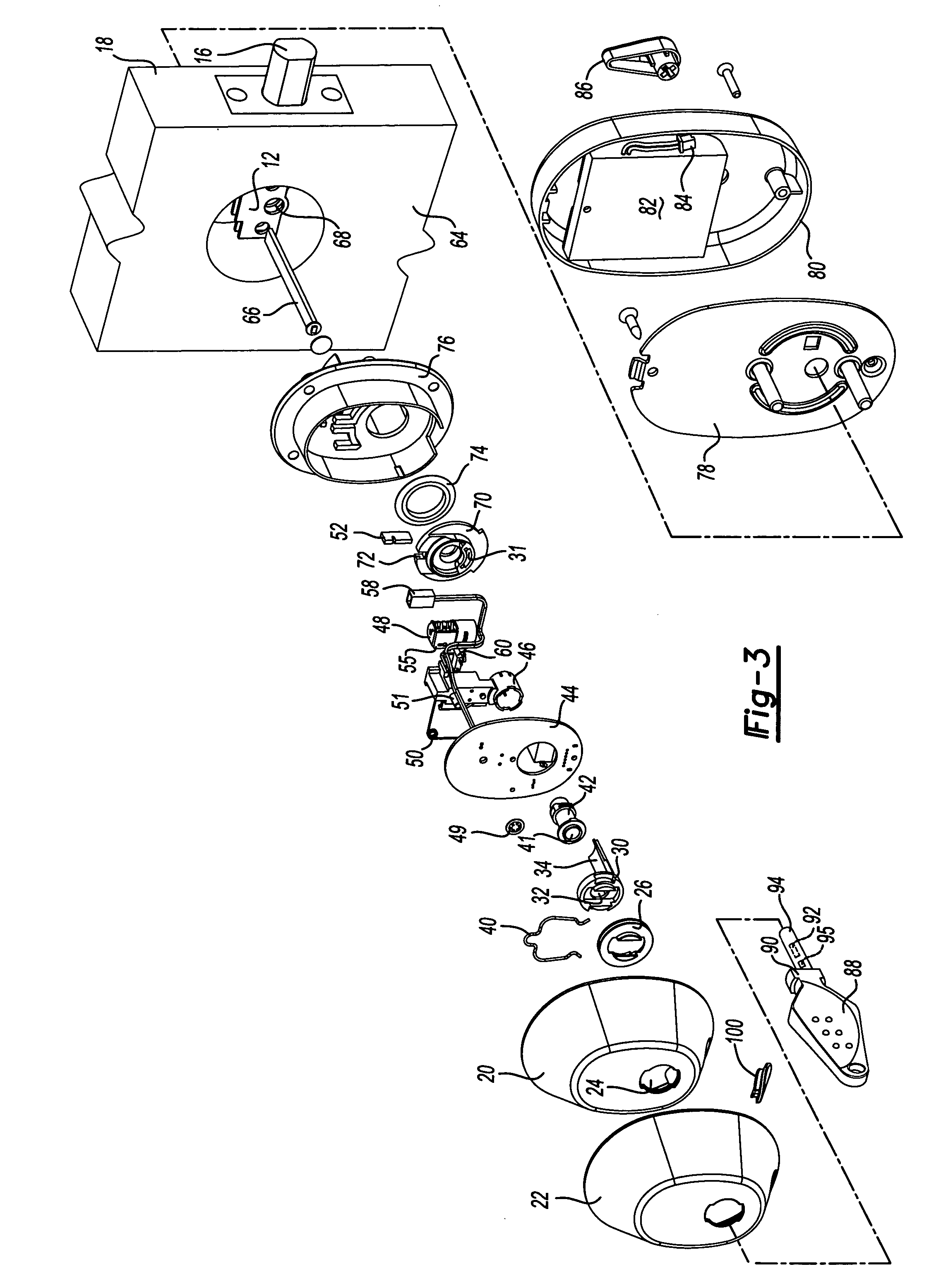
[0018] Referring to FIG. 3, the lock assembly 14 is shown in an exploded view to illustrate each of the corresponding parts. The lock assembly 14 includes an outer housing 20 that covers several different internal mechanisms. The outer housing 20 is an oval shaped domed member that defines an inner chamber into which the several mechanical e...


PUM


Abstract

An electronic lock assembly is actuated by a key including a transponder. The key is received within a coil assembly of the lock assembly. The key engages a switch that powers the coil assembly. The coil assembly generates a magnetic field that energizes the transponder. The transponder transmits a signal received by a controller. The controller actuates the lock assembly responsive to the received signal to move a locking member to an unlocked position. The key may then move to unlatch a latch associated with the lock assembly. As the key provides the energy required for unlatching the latch further energization of the motor is not required. The lock assembly provides for the actuation and energization of the transponder with small amounts electrical energy such that the lock assembly may be powered by commercially available batteries for a practical operational life.

Description

BACKGROUND OF THE INVENTION [0001] This invention is generally related to an electronic door lock. More particularly, this invention relates to an electronic door lock that utilizes a radio frequency identification tag to actuate and allow access to the lock. [0002] Typically, an electronic door lock utilizes one of several varieties of credentials to allow access to the lock. The credential can commonly come in the form of a magnetic strip key card, a smart card, a proximity badge, or simply the use of a pin code. The use of magnetic strip key cards, smart cards, and proximity badges have certain disadvantages. In many applications the lock will include a card reader into which the key card or smart card is inserted. The key card and smart card will include a magnetic strip that stores a code or other access algorithm that is read by the electronic lock. If the code on the key card or the smart card matches some predefined criteria, the electronic lock will allow access and opening...

Claims


Application Information

Patent Timeline
Patent Type & Authority Applications(United States)
IPC IPC(8): H04Q1/00G05B19/00
CPCE05B15/1614E05B47/0673E05B65/0032G07C2009/00777E05B2047/0058G07C9/00309E05B2047/0031
Inventor WRIGHT, MICHAEL J.MOON, CHARLES W.MITCHELL, ERNST KERNTRAN, TUAN A.BEIGEL, MICHAEL L.REMENIH, MIKEWALDRON, SCOTT M.
Owner COMPIZED SECURITY SYST
Why Eureka
Try Eureka