Method and apparatus for direction finding

a direction finding and direction technology, applied in the direction of multi-channel direction-finding systems using radio waves, instruments, measurement devices, etc., can solve the problems of not being able to find the direction on a signal that had disappeared, the requirement of troublesome, and the emitter could come on briefly and then disappear, so as to improve the accuracy of the bearing line

Active Publication Date: 2006-10-12
BAE SYST INFORMATION & ELECTRONICS SYST INTERGRATION INC
View PDF3 Cites 19 Cited by
  • Summary
  • Abstract
  • Description
  • Claims
  • Application Information

AI Technical Summary

Benefits of technology

[0044] Thus, in addition to allowing direction finding on every signal, the subject system allows one

Problems solved by technology

This has proved to be a troublesome requirement, especially with prior architectures.
Moreover, a more important problem was that the emitters could come on briefly and then disappear.
As will be appreciated, in prior DF systems it was not possible to direction-find on a signal that had disappeared.
Moreover, the prior DF systems were based on narrow band receivers, which never were able to keep up with all of the new energy alarms that were coming in.
With the present proliferation of emitters, the older narrow bandwidth systems are not able to keep up with even a significant percentage of the load.
However, by merely duplicating the number of full-up direction finding systems, one would have the complication of coordinating between the direction finders.
Moreover, aside from the coordination problem, one would require extra sets of hardware, involving more power, more heat, more cooling, increased weight, increased physical size, and increased cost.
However, if one divides the available power at the antenna elements between all of the direction finding systems, one loses power per channel.
This means that the ability to direction-find on a low-level signal, which is always a problem, gets even more exacerbated.
Thus, there did not appear to be a solution to the requirement of being able to direction-find on two orders of magnitude

Method used


Image

  • Method and apparatus for direction finding
  • Method and apparatus for direction finding
  • Method and apparatus for direction finding

Examples


Embodiment Construction

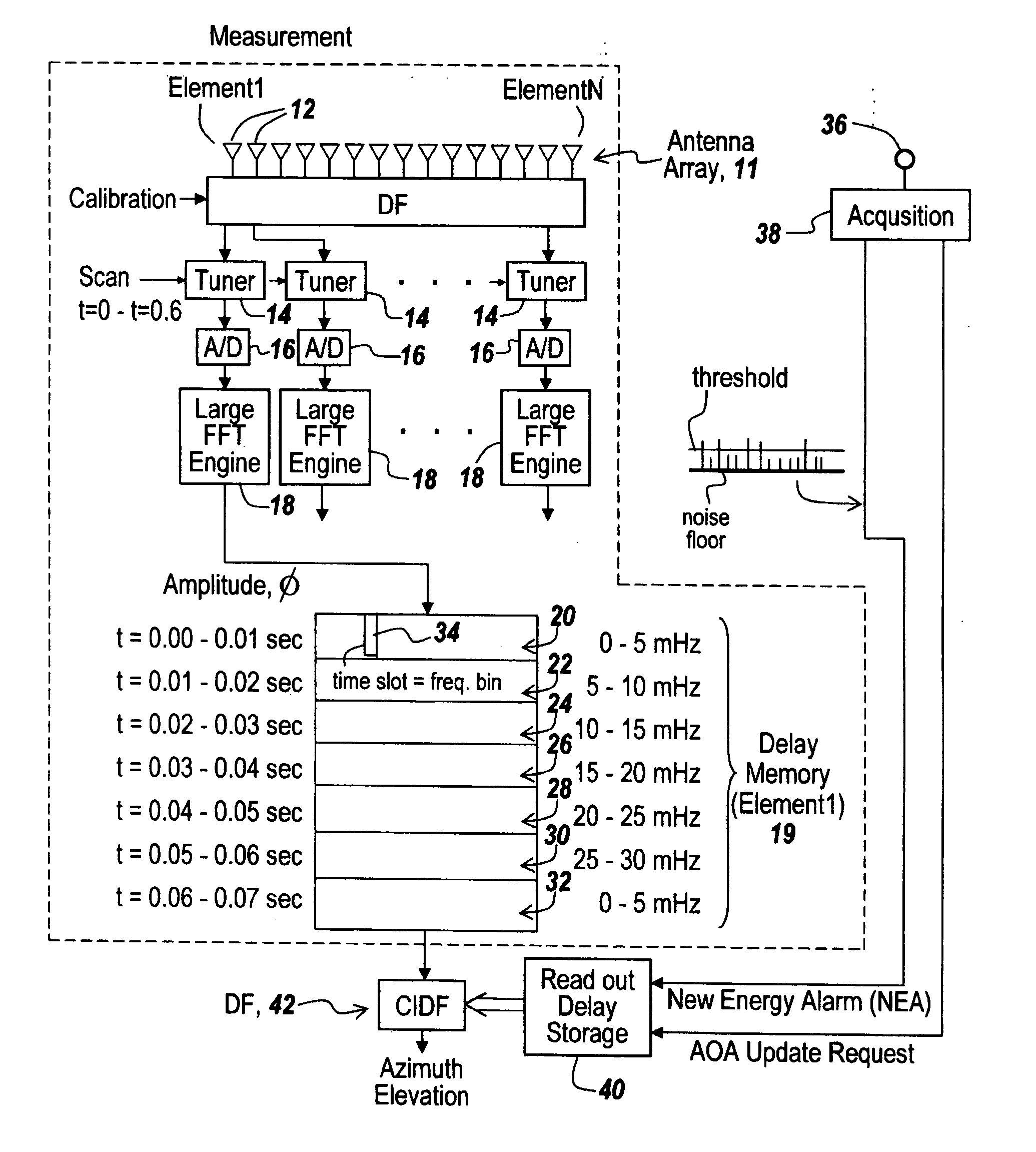
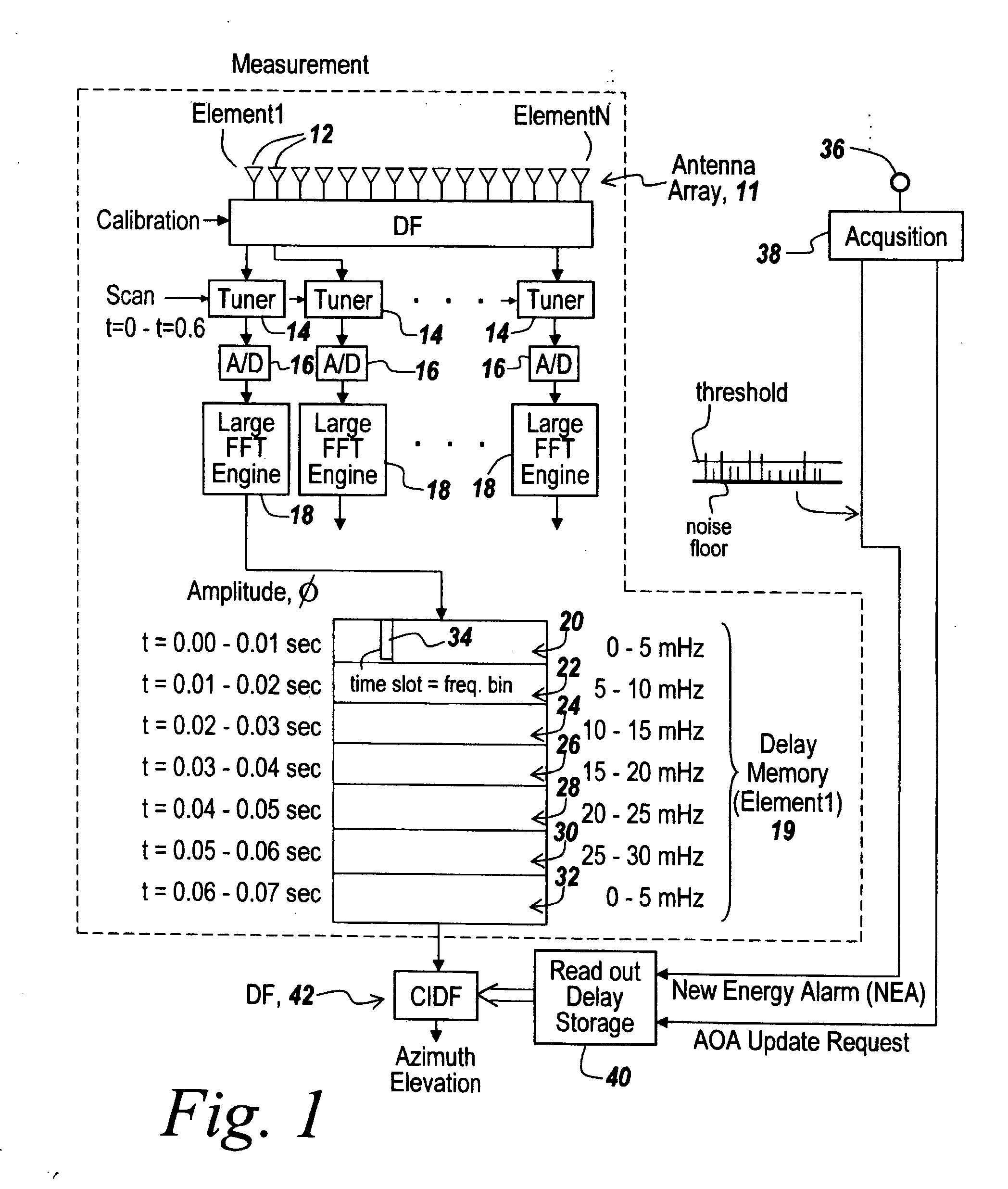
[0052] Referring now to FIG. 1, in one embodiment, as part of separating out the processing, a measurement section indicated by dotted line 10 is provided including an antenna array 11 that is coherently sampled by coherently sampling antenna elements 12, with the output of every antenna element being supplied to its own tuner 14 and then to an associated analog-to-digital converter 16, the output of which is directly coupled to a very large Fast Fourier Transform engine 18. The outputs of all of the FFT engines are coupled to delay storage 19, that in turn is segmented into frequency bands as illustrated at 20-32 into which data relating to amplitude and phase is stored in frequency bins, one of which being illustrated at 34.

[0053] In one embodiment the Transform is a 16-K transform. With modern computers, one can do very large FFTs in a very short period of time. Very large FFTs can convert large numbers of samples, meaning that one could process very large bandwidths, for instan...


PUM


Abstract

A direction finding system is used in which a number of adjacent bands are sequentially measured in fast rotation, with the results from each of the bands being FFT processed to provide amplitude and phase information on all of the signals existing within the band. Upon ascertaining that one wishes to do a direction finding process, one merely accesses the information in the delay memory so that direction finding resources are only allocated to signals of interest and such that one does not have to re-do an FFT upon finding a signal of interest.

Description

RELATED APPLICATIONS [0001] This Application claims rights under 35 USC § 119(e) from U.S. Application Ser. No. 60 / 669,148 filed Apr. 7, 2005, the contents of which are incorporated herein by reference.FIELD OF THE INVENTION [0002] This invention relates to direction finding and more particularly to a broadband scanning direction finding system capable of simultaneous direction-finding on large numbers of emitters. BACKGROUND OF THE INVENTION [0003] It has always been a priority for signal intelligence to be able to detect the presence of new energy from emitters and to obtain not only the azimuth in terms of the line of bearing (LOB) to the emitter but also elevation of the incoming signal so as to be able to locate the emitter. [0004] In so doing, one can ascertain the position of the emitter and its distance from the detector array, thereby to permit deploying countermeasures. [0005] In the past, namely in the 1960s and '70s, the requirement was to be able to detect and classify ...

Claims


Application Information

Patent Timeline
IPC IPC(8): G01S5/04
CPCG01S3/74
Inventor VAUGHN, DAVID A. JR.
Owner BAE SYST INFORMATION & ELECTRONICS SYST INTERGRATION INC
Why Eureka
Try Eureka