
Processing for distinguishing pen gestures and dynamic self-calibration of pen-based computing systems

a computing system and pen-based technology, applied in computing, electric digital data processing, instruments, etc., can solve the problems of affecting the ability of the pen to quickly or correctly recognize other pen operations or gestures, the pen will skid or move a substantial amount, and it is difficult to perform a tap gestur

Active Publication Date: 2006-10-12
MICROSOFT TECH LICENSING LLC
View PDF11 Cites 145 Cited by
  • Summary
  • Abstract
  • Description
  • Claims
  • Application Information

AI Technical Summary

Benefits of technology

[0014] Aspects of the present invention also relate to systems and methods for dynamically self-calibrating a computer system, e.g., calibrating a displayed input panel view with respect to input data recognized and received by a digitizer. Such systems and methods may include: (a) receiving plural user inputs directed toward a first target (e.g., via an input system, optionally including a digitizer and/or display screen); (b) determining first offset data for at least some of the plural user inputs directed toward the first target (e.g., using a computer processor system, such as one or more microprocessors), wherein the first offset data indicates a difference in at least one of distance or direction between a visual location of the first target (e.g., as shown on a display device) and a hardware location (e.g., on a digitizer) corresponding to the visual location of the first target; (c) receiving plural user inputs directed toward a second target (e.g., at a computer processor system, such as one or more microprocessors); (d) determining second offset data for at least some of the plural user inputs directed toward the second target (e.g., using a computer processor system, such as one or more microprocessors), wherein the second offset data indicates a difference in at least one of distance or direction between a visual location of the second target (e.g., as shown on a display device) and a hardware location (e.g., on the digitizer) corresponding to the visual location of the second target; (e) determining if the first offset data differs from the second offset data by more than a threshold amount (e.g., in distance and/or direction, for example, using a computer processor system, such as one or more microprocessors); and (f) changing at least some calibration data associated with the second position, in at least some instances, when

Problems solved by technology

In many situations, however, improving the pen-based computing system's ability to correctly recognize one or more types of system gestures will degrade its ability to quickly or correctly recognize other pen operations or gestures, sometimes even very basic pen operations or gestures.
Often, particularly when people casually tap the pen down on the digitizer surface, the pen will skid or move a substantial amount during those few milliseconds while it is in contact with the digitizer.
Such strict input threshold parameters would make it difficult to perform a tap gesture, which would be very frustrating to users.
On the other hand, this extended delay results in a perceived latency when the user does not intend to make a tap gesture.
More specifically, when users intend to enter electronic input ink or perform a dragging operation, the user may feel as if the system is freezing briefly, almost as if the system is not capable of keeping up with the user input, because the system delays to determine whether a sloppy tap was input rather than the ink or drag input.
Therefore, this “balancing act” can degrade the quality of drawing and dragging operations and the user's experience with pen-based computing systems.
The “tap” vs. ink entry and / or dragging operations are not the only gesture operations that may cause recognition delays in pen-based computing systems.
Pen-based computing systems also have “calibration” issues, issues that are not experienced with at least some other types of computing systems.
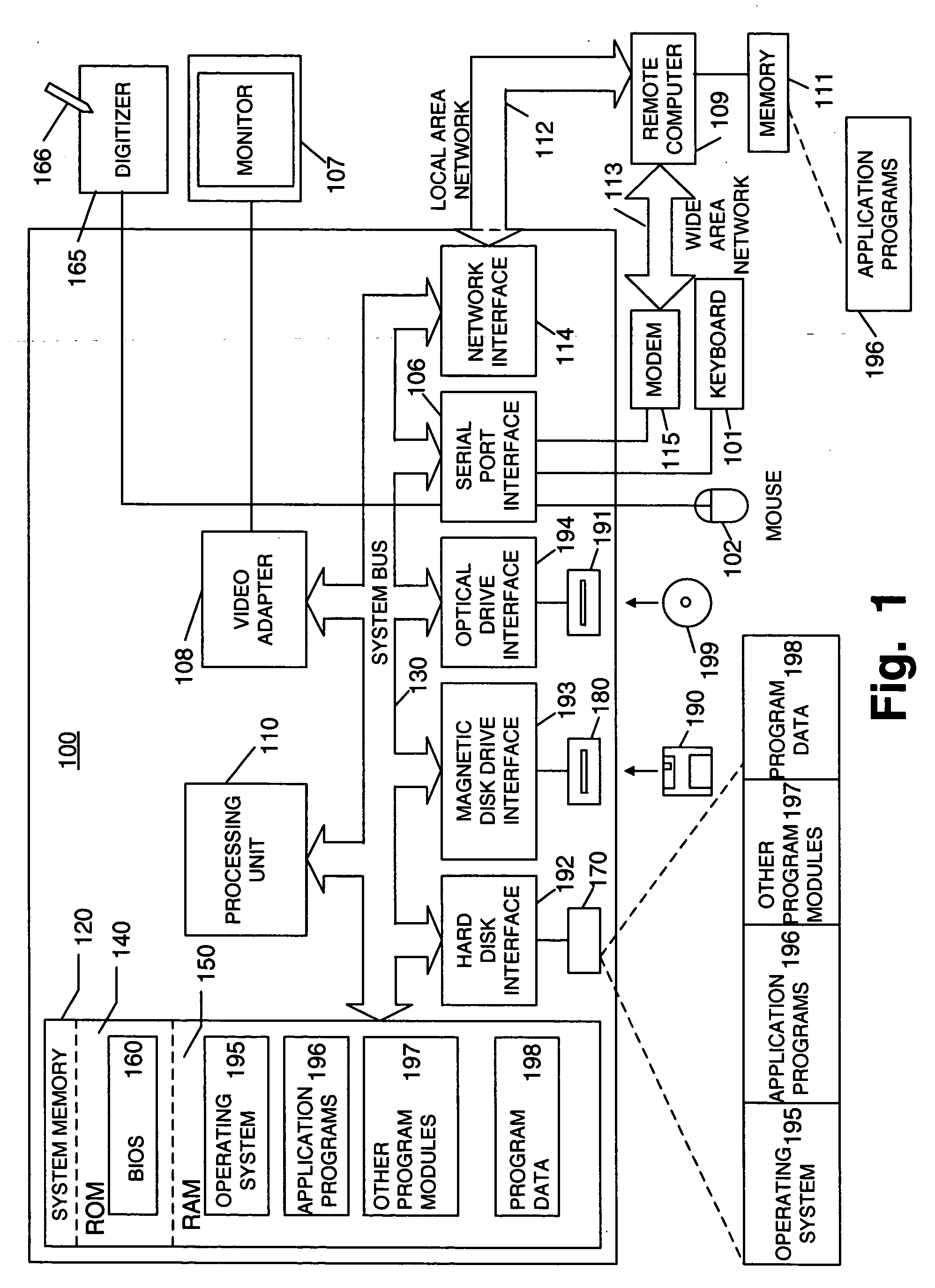
For example, due to mechanical limitations relating to pens, displays, and digitizers, the digitizer hardware typically reports interaction pen positions (e.g., X,Y coordinates) that do not exactly match the location on the display where the visual target is located (e.g., this may occur because the display device that generates the visual target is different and independent from the digitizer device used to recognize the location of pen during input interaction).
Other sources of calibration issues may include, for example: electromagnetic noise caused by hard drives and / or power supplies, sensitivity characteristics of the digitizer hardware (e.g., the digitizer's sensitivity may change with temperature, elevation, humidity, etc., such that its behavior does not stabilize until after a “break-in” period, and correct, perfect calibration is not possible from the factory due to this “break-in” period, etc.), and the like.
However, in practice, this difference can be quite significant.
While the limitations in extending the calibration data from one machine to other, independent machines are readily apparent, it would cost too much in time delays to perform this complex calibration procedure on every machine coming off the line.
Other hardware manufacturers may do little or no actual calibration and rely on the likelihood that their manufacturing procedures have closely aligned the digitizer and the LCD screen and / or that the underlying circuitry of the computing system will not generate sufficient noise to substantially disturb the actual user experience.
The limitations inherent in these calibration procedures (or lack thereof) are readily apparent, and these procedures do nothing to correct for calibration drift that occurs over time and / or system noise generated by electronic components making up the system.
Moreover, the calibration activities and effectiveness available in such modes can be relatively limited.
Even when conducted, these user-initiated calibration procedures typically are time-consuming, inconvenient, and temporary fixes.

Method used


Image

  • Processing for distinguishing pen gestures and dynamic self-calibration of pen-based computing systems
  • Processing for distinguishing pen gestures and dynamic self-calibration of pen-based computing systems
  • Processing for distinguishing pen gestures and dynamic self-calibration of pen-based computing systems

Examples


Embodiment Construction

[0022] As described above, aspects of the present invention relate to systems, methods, and computer-readable media for processing and using input information in pen-based computing systems, e.g., for better recognizing input gestures and / or for better calibrating the system hardware. The following description is divided into sub-sections to assist the reader. The sub-sections include: Terms; General Description of Various Aspects of the Invention; Example Hardware; Example Systems, Methods, and Computer-Readable Media According to the Invention; and Conclusion.

I. TERMS

[0023] The following terms are used in this specification and, unless otherwise specified or clear from the context, the terms have the meanings provided below:

[0024]“Ink” (also called “digital ink” or “electronic ink”)—A sequence or set of handwritten strokes. A sequence of strokes may include strokes in an ordered form. The sequence may be ordered in any suitable manner, such as by the time the stroke was capture...


PUM


Abstract

Systems, methods, and computer-readable media process and distinguish user input device gestures, such as gestures input via a pen in a pen-based computing system, e.g., to quickly and reliably distinguish between electronic ink entry, single taps, double taps, press-and-hold actions, dragging operations, and the like. Systems, methods, and computer-readable media also are provided for dynamically calibrating a computer system, e.g., calibrating a displayed input panel view based on input data recognized and received by a digitizer. Such systems and methods may operate without entering a dedicated or special calibration application, program, or routine.

Description

FIELD OF THE INVENTION [0001] The present invention generally relates to systems, methods, and computer-readable media with computer-executable instructions stored thereon for processing and / or distinguishing various pen gestures from one another, e.g., in pen-based computing systems. Additional aspects of this invention relate to systems, methods, and computer-readable media for dynamically self-calibrating computer displays, digitizers, and / or input systems, for e.g., pen-based computing systems. BACKGROUND [0002] Typical computer systems, especially computer systems using graphical user interfaces (GUIs), are optimized for accepting user input from one or more discrete input devices, such as a keyboard for entering text, and a pointing device, such as a mouse with one or more buttons, for operating the user interface. An example of such a GUI is the user interface for the Windows® computer operating system (available from Microsoft Corporation of Redmond, Wash.). The ubiquitous k...

Claims


Application Information

Patent Timeline
IPC IPC(8): G09G5/00G06F3/041
CPCG06F3/0418G06F3/017G06F3/04883G06F3/03545G06F3/04845
Inventor ZOTOV, ALEXANDER J.TOWNSEND, REEDDODGE, STEVEN P.
Owner MICROSOFT TECH LICENSING LLC
Learn More