Eureka AIR delivers breakthrough ideas for toughest innovation challenges, trusted by R&D personnel around the world.

Image detection and identification device

Active Publication Date: 2006-10-12
NORTHROP GRUMMAN SYST CORP
View PDF6 Cites 5 Cited by
  • Summary
  • Abstract
  • Description
  • Claims
  • Application Information

AI Technical Summary

Benefits of technology

[0013] All spectral and / or broadband information is contained in one frame of image data produced by the focal plane array, making image processing more streamlined and the time required to collect all of the necessary data minimal.

Problems solved by technology

While the systems described are collecting this spectral information, they cannot collect broadband image information.
Another problem is that in order to locate the source of a light-emitting event within the sensors' field of view in the case where the spectral separation element or subassembly rotates, the spectral separation element or subassembly must rotate enough to generate an arc in the light spectrum received by the focal plane array that is collected over several frames of the focal plane array in order to locate the position of the light-emitting event.
Another problem associated with the prior art imaging devices is that the prior art imaging devices must be stable for proper operation.

Method used


Image

  • Image detection and identification device
  • Image detection and identification device
  • Image detection and identification device

Examples


Embodiment Construction

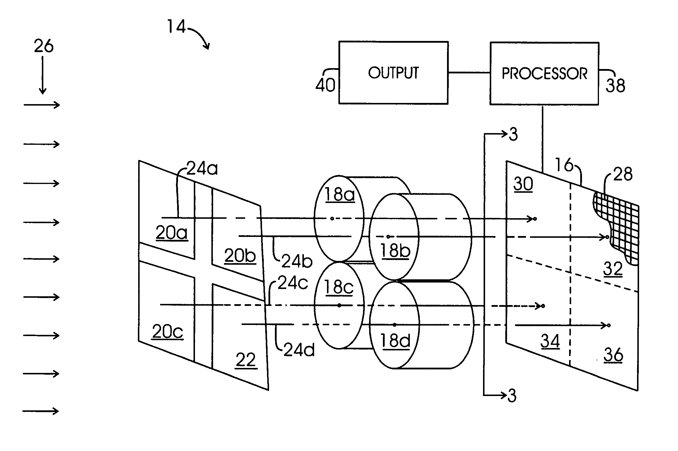
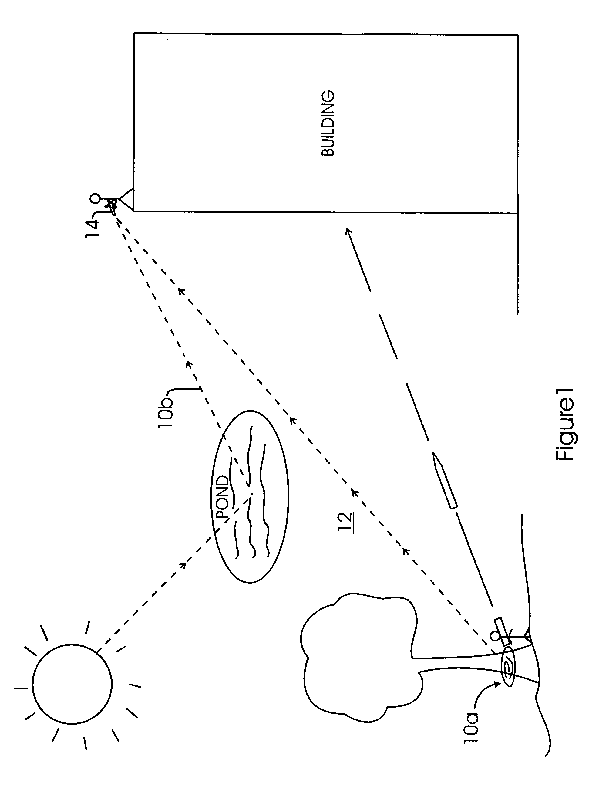
[0021] The drawings referred to herein are for the purpose of illustrating the preferred embodiments of the present invention and not for the purposes of limiting the same. For example, certain portions of the detailed description make reference to detecting and identifying a single light emitting event 10a within a scene 12. However, it is also contemplated within the scope of the present invention that the aspects of the present invention described herein may detect and identify two simultaneous light emitting events 10a within the scene 12.

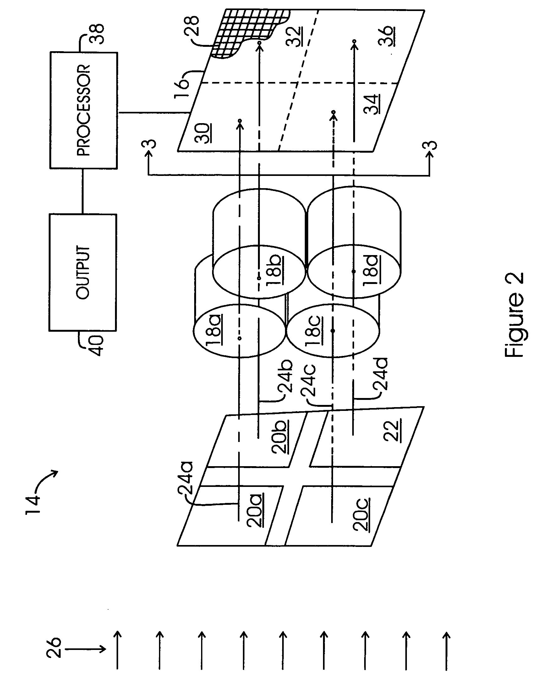
[0022] An imaging device 14 (see FIGS. 1, 2 and 4) may be provided. The imaging device 14 may be for the purpose of detecting-and identifying the light emitting event 10a. The light emitting event 10a may occur within the scene 12. Also, other light emitting events 10b may also occur within the scene 12. For example, as shown in FIG. 1, light emitting events 10a, 10b may occur simultaneously within the scene 12. Light emitting event 10a shown ...


PUM


Abstract

An imaging device is provided which may include a plurality of imaging lenses. Each imaging lens may be placed adjacent to a dispersive element. The imaging lenses and dispersive element(s) may be placed adjacent to a focal plane array to allow light from a light emitting event traveling through the imaging lenses to be simultaneously received by the focal plane array. One of the optical channels provides continuous broadband imagery without interfering with the operation of the dispersive optical channels. No moving parts are required in this small compact system, and no reconfiguration during operation is necessary to enable any of the functions, they are all simultaneous. Information related to the light received by the focal plane array may be transmitted to a processor for processing to determine whether the light emitting event is of interest and to determine an event type. Broadband imagery provided may be used for situational awareness, targeting, and surveillance.

Description

CROSS-REFERENCE TO RELATED APPLICATIONS [0001] Not Applicable STATEMENT RE: FEDERALLY SPONSORED RESEARCH / DEVELOPMENT [0002] Not Applicable BACKGROUND OF THE INVENTION [0003] The present invention relates generally to imaging devices, and more particularly to devices for detecting and identifying light emitting events. [0004] Prior art imaging devices may comprise a rotating spectral separation element or subassembly installed in the collimated space of an imaging lens that is focused on a focal plane array and then may use spectro-tomographic image processing techniques to extract hyperspectral image data. Prior art imaging devices also may comprise a spectral separation element or subassembly placed in front of the imaging lens of a single channel imaging system comprised of an imaging lens focused on a focal plane array. The prior art imaging devices may receive light from a light-emitting event occurring within a scene. The emitted light travels through the spectral separation el...

Claims


Application Information

Patent Timeline
IPC IPC(8): G01J3/28
CPCG01J3/02G01J3/36G01J3/2823G01J3/0256
Inventor KAUFFMAN, CHRISTOPHER L.YOO, SUNG-SHIKHARKRIDER, CURTISMINARIK, PHILIP
Owner NORTHROP GRUMMAN SYST CORP
Why Eureka
Eureka Blog
Learn More