Blood collection and measurement apparatus

Inactive Publication Date: 2006-10-12
CHROMEDX
View PDF21 Cites 58 Cited by
  • Summary
  • Abstract
  • Description
  • Claims
  • Application Information

AI Technical Summary

Problems solved by technology

In general, conventional methods of collecting and analyzing blood leads to inevitable delays, unnecessary handling of the blood and the introduction of contaminants, which are all known sources of analysis error.
The eventual transfer of blood between vessels delays the actual analysis of the blood sample and also exposes the blood sample to contaminants.
Such reagents dilute a blood sample and cause significant errors if the volume of the blood sample is small.
Arterial blood must be collected by a doctor or a specially-trained technician, using a syringe, because of a number of inherent

Method used


Image

  • Blood collection and measurement apparatus
  • Blood collection and measurement apparatus
  • Blood collection and measurement apparatus

Examples


second embodiment

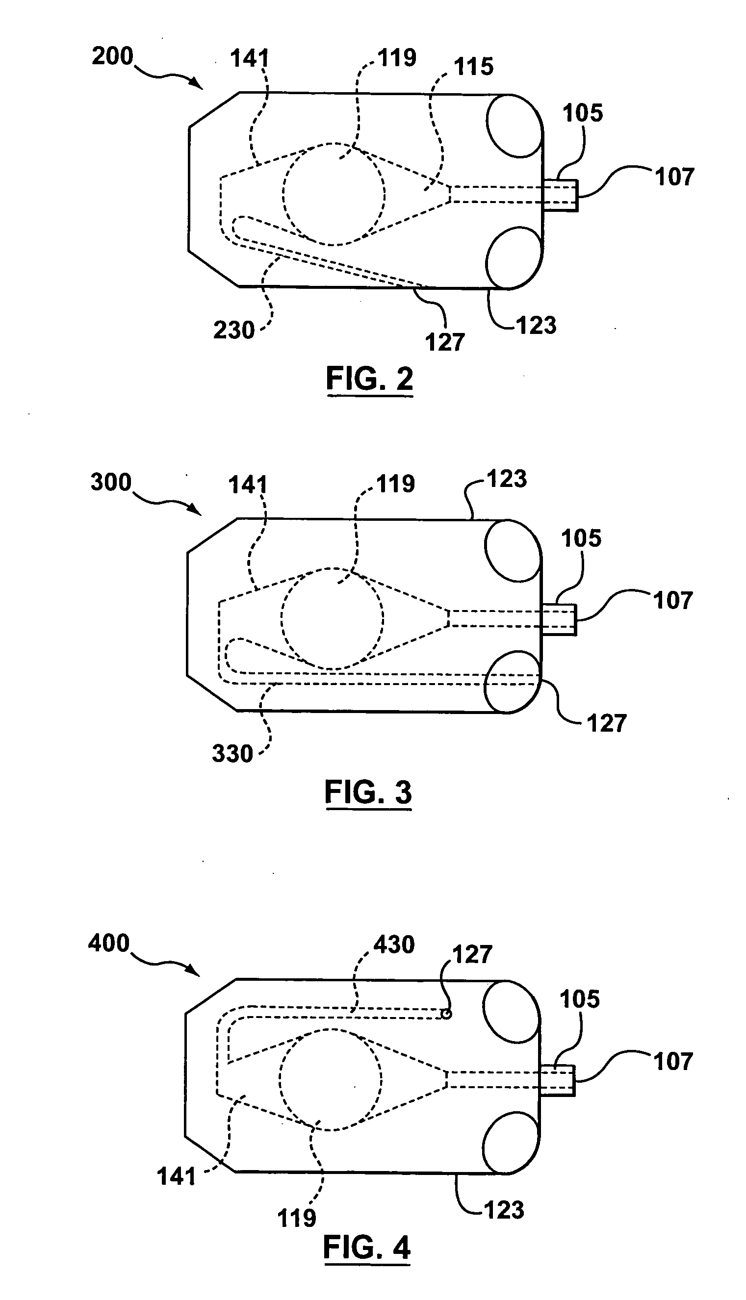
[0035] Referring to FIG. 2, shown is a top view of an apparatus 200 suitable for both the collection and measurement of a blood sample according to the invention. The apparatus 200 illustrated in FIG. 2 is similar to the apparatus 100 illustrated in FIG. 1, and accordingly, elements common to both share common reference numerals. The primary difference, illustrated in FIG. 2, is that the vent 127 is now located on a lateral side of the housing 123 as opposed to being directly opposite the inlet 107 along a shared axis. In order to accommodate the new location of the vent 127, a curved outlet capillary tube 230 fluidly connects the rear of the overflow chamber 141 to the vent 127 on the lateral side of the housing 123.

third embodiment

[0036] Referring to FIG. 3, shown is a top view of an apparatus 300 suitable for both the collection and measurement of a blood sample according to the invention. The apparatus 300 illustrated in FIG. 3 is similar to the apparatus 100 illustrated in FIG. 1, and accordingly, elements common to both share common reference numerals. The primary difference, illustrated in FIG. 3, is that the vent 127 is now located on the same side of the housing 123 as the inlet 107. In order to accommodate the new location of the vent 127, an L-shaped capillary tube 330 fluidly connects the rear of the overflow chamber 141 to the vent 127 on the front side of the housing 123.

fourth embodiment

[0037] Referring to FIG. 4, shown is a top view of an apparatus 400 suitable for both the collection and measurement of a blood sample according to the invention. The apparatus 400 illustrated in FIG. 4 is similar to the apparatus 100 illustrated in FIG. 1, and accordingly, elements common to both share common reference numerals. The primary difference, illustrated in FIG. 4, is that the vent 127 is now located on the top surface 123a of the housing 123 as opposed to directly opposite the inlet 107 along a shared axis. In order to accommodate the new location of the vent 127, an L-shaped capillary tube 430 fluidly connects the rear of the overflow chamber 141 to the vent 127 on the top surface 123a of the housing 123. Moreover, in comparison with the apparatus 300 shown in FIG. 3, the L-shaped capillary tube 430 is similar to the L-shaped capillary tube 330 with the exception that the L-shaped capillary tube 430 does not extend all the way to the front side of the housing 123, but i...


PUM


Abstract

Some embodiments of the invention provide one apparatus that is suitable for both the collection and measurement of a blood sample. Once a blood sample is drawn into such an apparatus the blood sample can be analyzed, without having to transfer any portion of the blood sample into another vessel. Also, in some very specific embodiments, the apparatus is provided with an optical chamber that is specifically designed to reduce the average attenuation of electromagnetic radiation (EMR) due to scattering of EMR by the red blood cells in a blood sample, without having to hemolyze the red blood cells by using sound waves or by adding reagents to the blood sample. Moreover, as a result of the time saved by using a single apparatus for blood sample collection and measurement, the addition of an anticoagulant is not required to prevent clotting. Moreover, in such embodiments the optical chamber is designed to spread blood into a thin film, thereby reducing the incidences of trapped air bubbles in the collected blood sample in the optical chamber. Instead air bubbles are easily pushed through the optical chamber and guided out of the apparatus through a vent. Optionally, at least one biosensor may be provided within a second flow path in the apparatus.

Description

FIELD OF THE INVENTION [0001] The invention relates to blood analysis, and, in particular to an apparatus used in both the collection and measurement of a blood sample. BACKGROUND OF THE INVENTION [0002] There are many medical diagnostic tests that require a blood sample. In general, conventional methods of collecting and analyzing blood leads to inevitable delays, unnecessary handling of the blood and the introduction of contaminants, which are all known sources of analysis error. More specifically, as per convention, a blood sample is typically withdrawn using one instrument / vessel and then transferred into another vessel for analysis. For example, a syringe is used to obtain a relatively large blood sample that is later put into tests tubes. Syringe extraction of blood is beneficial in circumstances where several milliliters of blood are needed. Alternatively, much smaller blood samples (e.g. in the range of micro-liters) can be obtained using a pinprick and then a capillary tube...

Claims


Application Information

Patent Timeline
IPC IPC(8): G01N21/00
CPCB01L2300/0864G01N2021/054G01N21/03G01N21/11G01N21/274G01N33/49G01N2021/0314G01N2021/0346G01N2021/0382B01L3/502715B01L3/502723B01L2300/0636B01L2300/0654B01L2300/0816B01L2400/0406
Inventor SAMSOONDAR, JAMES
Owner CHROMEDX
Why Eureka
Try Eureka