Power source device

a technology of power source and safety plug, which is applied in the direction of electric devices, coupling device connections, battery/fuel cell control arrangements, etc., can solve the problem of not being able to release the insertion prevention unit of the safety plug, and achieve the effect of ensuring work safety

Inactive Publication Date: 2006-10-12
PANASONIC EV ENERGY CO LTD
View PDF7 Cites 20 Cited by
  • Summary
  • Abstract
  • Description
  • Claims
  • Application Information

AI Technical Summary

Benefits of technology

[0009] Therefore, it is an object of the present invention to provide a power source device including a battery pack, which allows a power distribution path of the battery pack to be opened and closed by insertion and removal of a safety plug, prevents a person other than a worker or a mandator of the worker from inserting the safety plug and closing the power distribution path, and ensures work safety.

Problems solved by technology

With this structure, when a worker removes the safety plug from the switch body and activates the insertion prevention unit for the safety plug, a person other than the worker and a mandator of the worker cannot release the insertion prevention unit for the safety plug.

Method used


Image

  • Power source device
  • Power source device
  • Power source device

Examples


Embodiment Construction

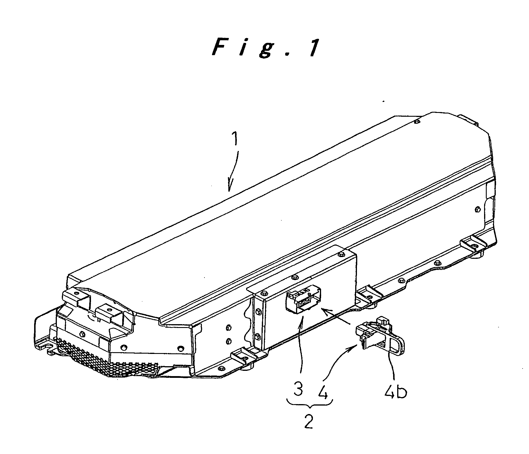
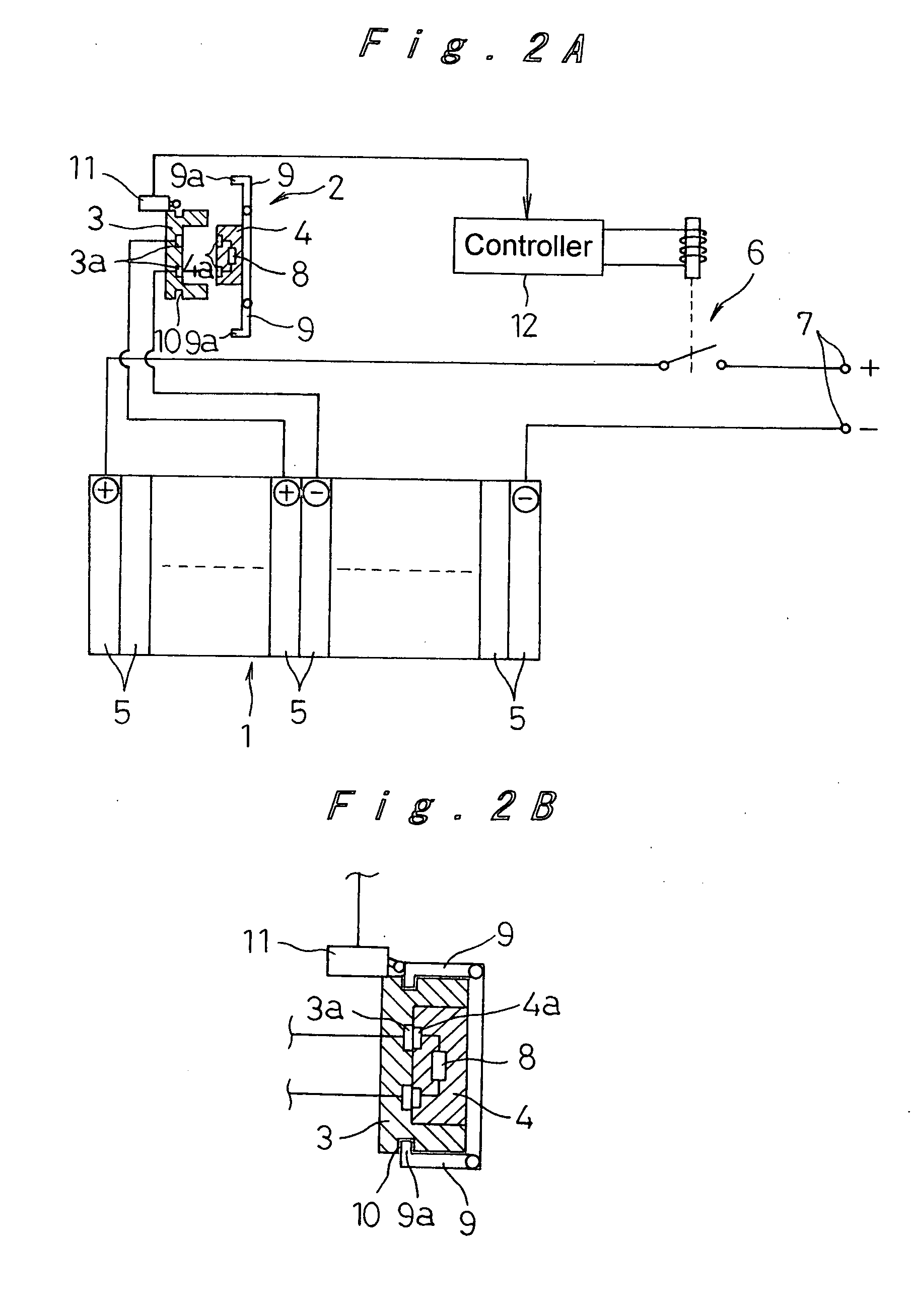
[0020] A power source device including a battery pack according to an embodiment of the present invention will be hereinafter described with reference to FIGS. 1 to 4B.

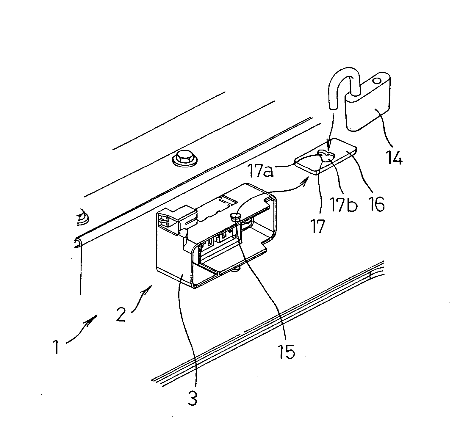
[0021] Referring to FIG. 1, a battery pack 1 for driving a vehicle is to be mounted on the vehicle and includes a battery assembly (not illustrated) therein. The battery assembly has a plurality of battery modules each of which includes a single cell (rechargeable battery) or a plurality of cells (rechargeable batteries) connected in series. The battery modules are arranged in parallel with a cooling path provided therebetween, and are assembled by binding end members provided at both ends of the arrangement of the battery modules, and are connected to one another in series. A path for supplying and discharging a cooling air to / from the respective cooling path between the battery modules is provided above and below the battery assembly. A charge and discharge monitoring unit (battery ECU) is provided on one side of t...


PUM


Abstract

In a power source device including a battery pack, a safety switch is provided between a given pair of battery modules connected to each other. The safety switch connects and disconnects those battery modules by insertion and removal of a safety plug to/form a switch body. The power source device also includes an insertion prevention unit, such as a lock, for preventing the insertion of the safety plug to the switch body in such a manner that prevention of the insertion of the safety plug is releasable. A release operation unit is kept by a worker who removes the safety plug, so that safety of the worker against electric shock is ensured.

Description

[0001] The present disclosure relates to subject matter contained in priority Japanese Patent Application No. 2005-114035, filed on Apr. 12, 2005, the contents of which is herein expressly incorporated by reference in its entirety. BACKGROUND OF THE INVENTION [0002] 1. Field of the Invention [0003] The present invention relates to a power source device including a battery pack. More particularly, the present invention relates to a power source device for ensuring worker's safety against electric shock. [0004] 2. Description of the Related Art [0005] There are various apparatuses using a power source device including a battery pack. The battery pack has a plurality of battery modules each of which includes a single cell or a plurality of cells connected in series, and which are connected in series. Examples of the apparatuses include an electric vehicle using the battery pack as a driving power source, a hybrid vehicle using the battery pack together with an internal-combustion engin...

Claims


Application Information

Patent Timeline
Patent Type & Authority Applications(United States)
IPC IPC(8): H01R13/44
CPCB60L3/04H01R13/443Y10S439/952B60L3/0046H01R13/6397B60L58/26B60L58/18Y02T10/70
Inventor MARUKAWA, SHUHEIMISU, MASAHIROETO, TOYOHIKO
Owner PANASONIC EV ENERGY CO LTD
Why Eureka
Try Eureka