

Anode cap, and voltage supply unit and image display apparatus utilizing the same
- Summary
- Abstract
- Description
- Claims
- Application Information
AI Technical Summary
Benefits of technology
Problems solved by technology
Method used
Image

Examples
Embodiment Construction
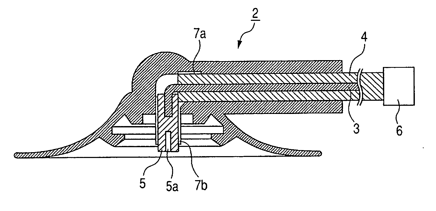
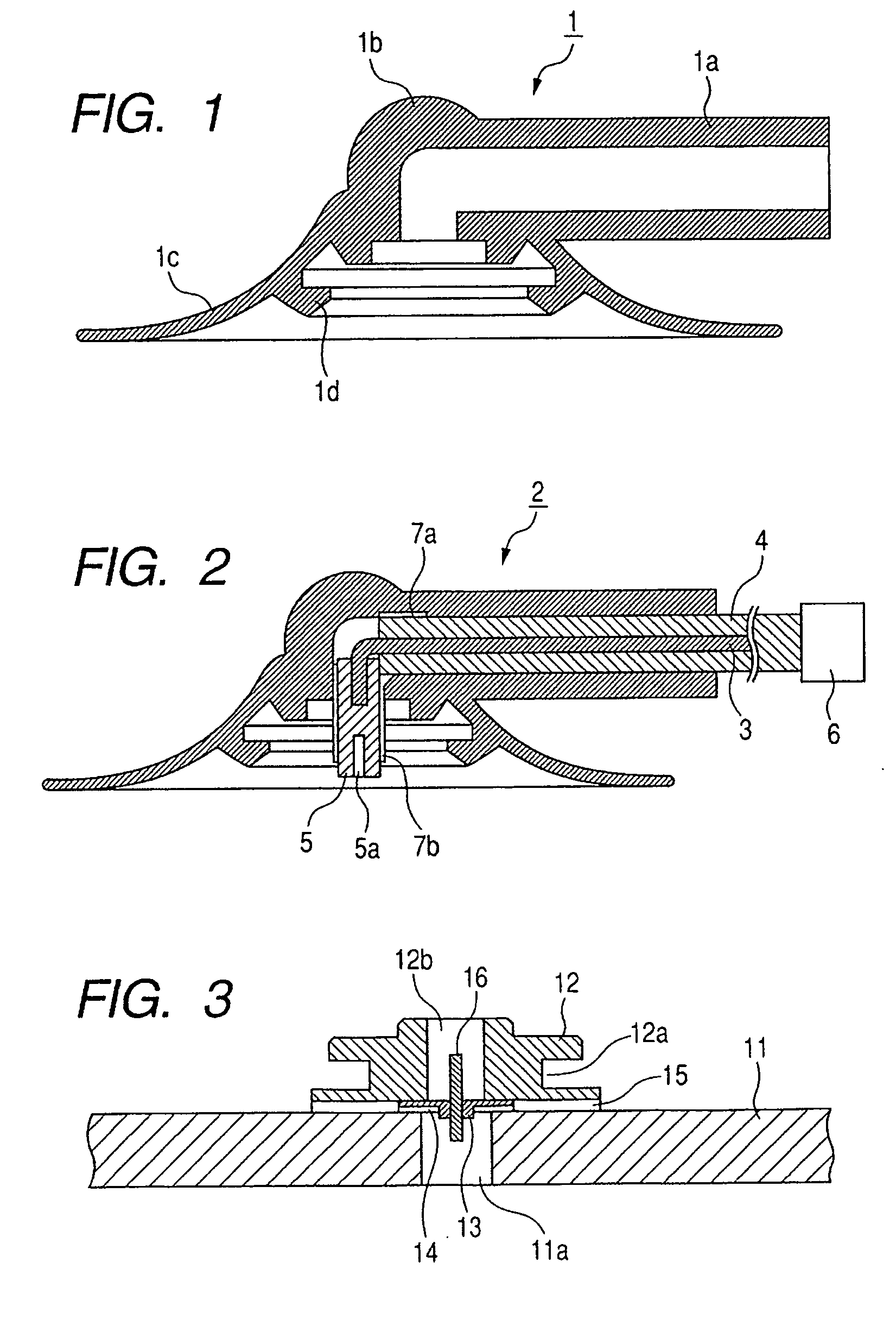
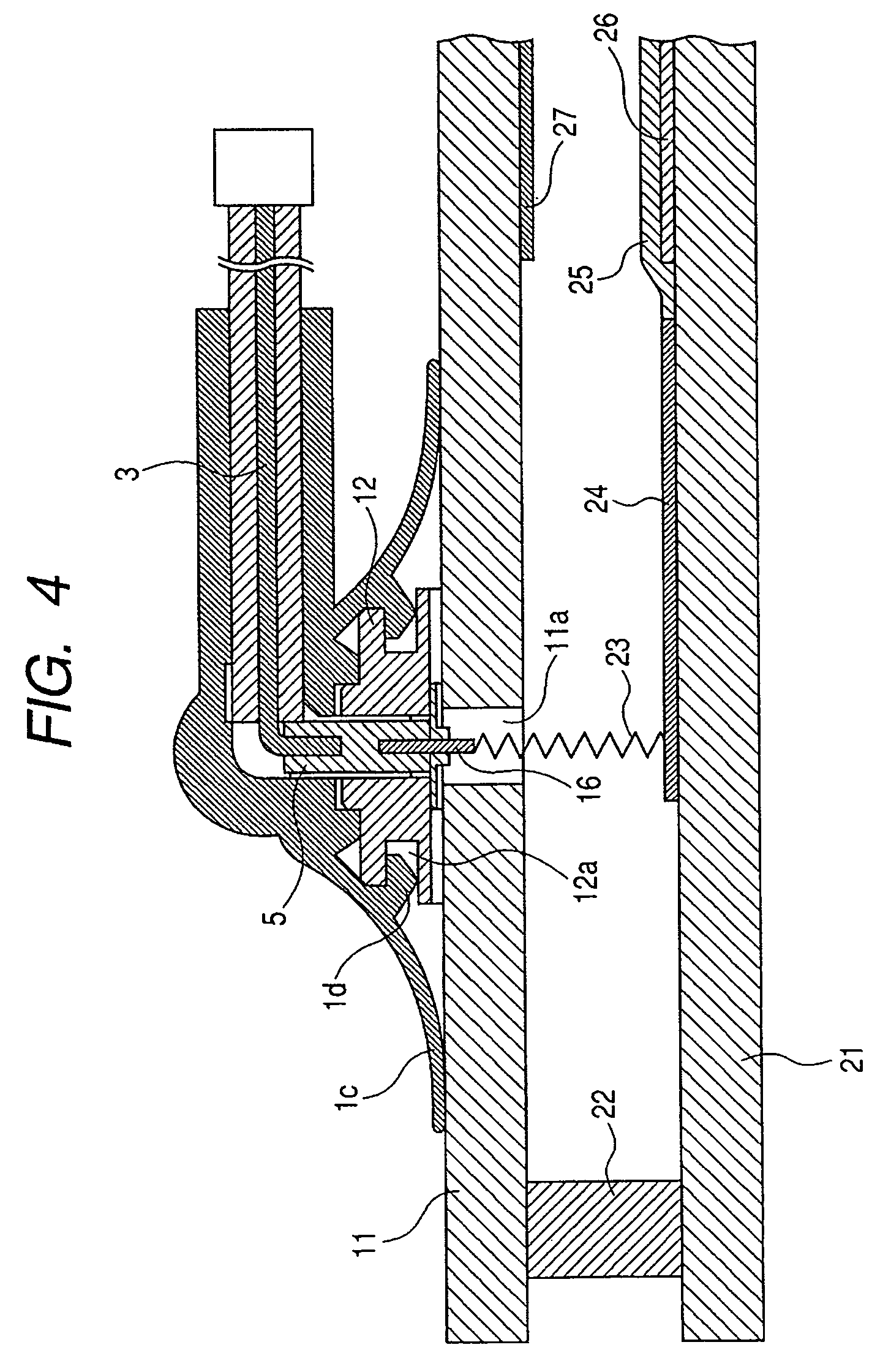
[0019] The present invention provides, in a first aspect thereof, an anode cap detachably attached to a display panel having an anode terminal on an external surface thereof, the anode cap including a holding unit for holding an end of an electroconductive wire for a voltage supply to the anode terminal, and an fastening portion for detachably fastened to a fixing member provided around the anode terminal.
[0020] Also the present invention provides, in a second aspect thereof, a voltage supply unit to be detachably attached to a display panel having an anode terminal on an external surface thereof, the voltage supply unit including an anode cap of the present invention and an electroconductive wire of which an end is supported by a holding unit of the anode cap.
[0021] Also the present invention provides, in a third aspect thereof, an image display apparatus provided with a display panel having an anode terminal on an external surface thereof, and a voltage supply unit for a voltage...
PUM
 Abstract
Description
Claims
Application Information