Current-collector metal foil, current collector, and current-collector-metal-foil manufacturing method

a manufacturing method and metal foil technology, applied in the field of current collector metal foil manufacturing method, can solve the problems of insufficient adherence to an active material and adherence of the active material to the metal foil, and achieve satisfactory electrical connection, reduce contact resistance with the active material, and reduce the effect of contact resistan

Active Publication Date: 2019-09-17
FURUKAWA SKY ALUMINUM CORP
View PDF47 Cites 0 Cited by
  • Summary
  • Abstract
  • Description
  • Claims
  • Application Information

AI Technical Summary

Benefits of technology

[0019]In addition, in the state in which active-material particles are fitted in the above-mentioned recessed parts, the surface area of the contact areas of the above-mentioned edge parts with the active-material particles is large compared with conventional metal foils. Therefore, in the above-mentioned metal foil, the contact resistance with the active material can be reduced.
[0020]As described above, in the above-mentioned metal foil, the active material tends not to peel off and the contact resistance with the active material can be decreased. Therefore, the above-mentioned metal foil can maintain, over the long term, a satisfactory electrical connection with the active material.
[0021]In addition, the above-mentioned current collector has an above-mentioned active-material-containing layer on a roughened surface of the above-mentioned metal foil, and the average aggregated particle size dave of the active material contained in the above-mentioned active-material-containing layer is 0.5 μm or more and 50 μm or less. Consequently, in the above-mentioned current collector, the particles of the above-mentioned active material tend to fit in the above-mentioned recessed parts, peeling of the above-mentioned active-material-containing layer can be reduced, and the contact resistance between the active material and the above-mentioned metal foil can be reduced. In addition, in devices such as secondary batteries and capacitors in which the above-mentioned current collector is used as an electrode, the electrode resistance originating from the above-mentioned low contact resistance can be easily reduced. As a result, the charging-discharging characteristics of the device can be improved, and charging and discharging can be performed at a high rate. In addition, because the device in which the above-mentioned current collector is used has the high adherence described above, high performance can be maintained over the long term.
[0022]In addition, in the above-mentioned current-collector-metal-foil manufacturing method, the above-mentioned metal foil can be prepared by transferring the contours of the above-mentioned pair of roughening rolls. The above-mentioned manufacturing method can control the contour of the above-mentioned metal foil with good reproducibility by using a technique called transfer. Consequently, as long as the contours of the above-mentioned roughening rolls are controlled, the shape and arrangement of the above-mentioned recessed parts easily can be made uniform over the entire length of the metal foil. As a result, the above-mentioned metal foil, having excellent quality, can be easily prepared. In addition, because the process of transferring the contours of the above-mentioned roughening rolls can be easily incorporated into preexisting metal-foil-manufacturing processes, the method of manufacturing the above-mentioned metal foil can be simplified and productivity can be increased.

Problems solved by technology

Nevertheless, the present situation is that, in metal foils manufactured using preexisting techniques, adherence to an active material is still insufficient, and there is a demand for further improvement.
In particular, if a powdered active material is used, then the adherence of the active material to the metal foil tends to decrease.

Method used


Image

  • Current-collector metal foil, current collector, and current-collector-metal-foil manufacturing method
  • Current-collector metal foil, current collector, and current-collector-metal-foil manufacturing method
  • Current-collector metal foil, current collector, and current-collector-metal-foil manufacturing method

Examples


working examples

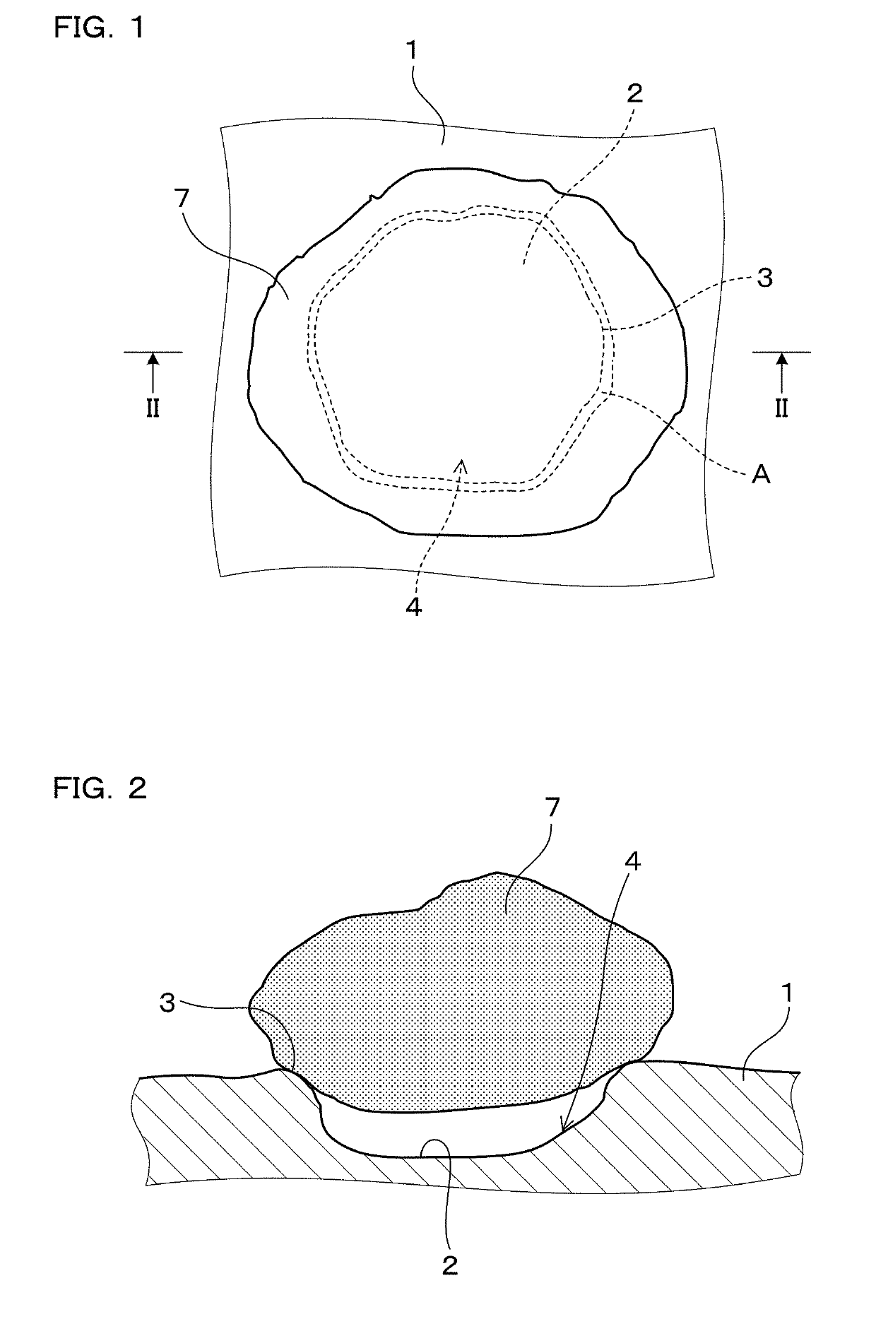
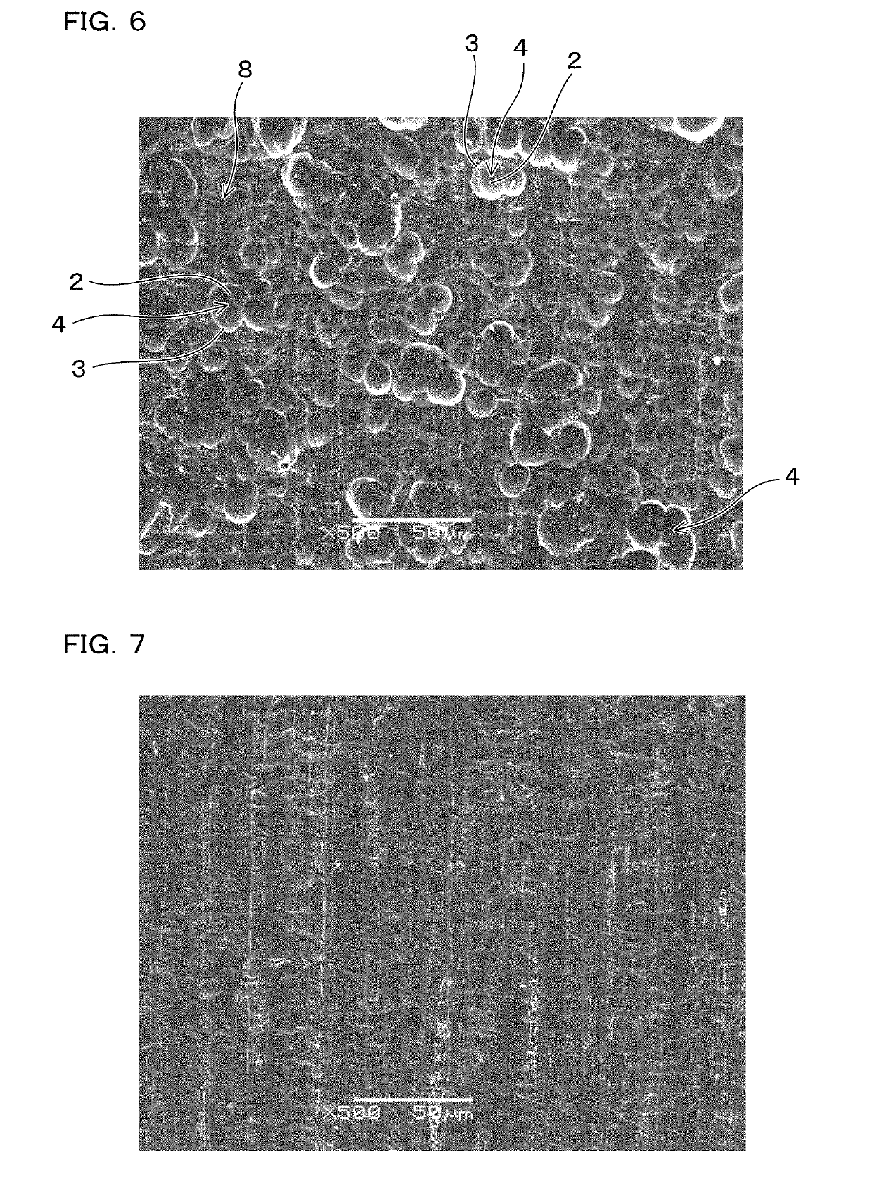
[0063]Working examples of the above-mentioned current-collector metal foils and the above-mentioned current collectors are explained below. A current-collector metal foil 1 comprises, on both surfaces, numerous recessed parts 4 (refer to FIG. 1 and FIG. 2), each recessed part 4 having a bottom-surface part 2, which is sunken down more than its periphery, and an edge part 3, which surrounds the bottom-surface part 2 and is raised above the bottom-surface part 2.

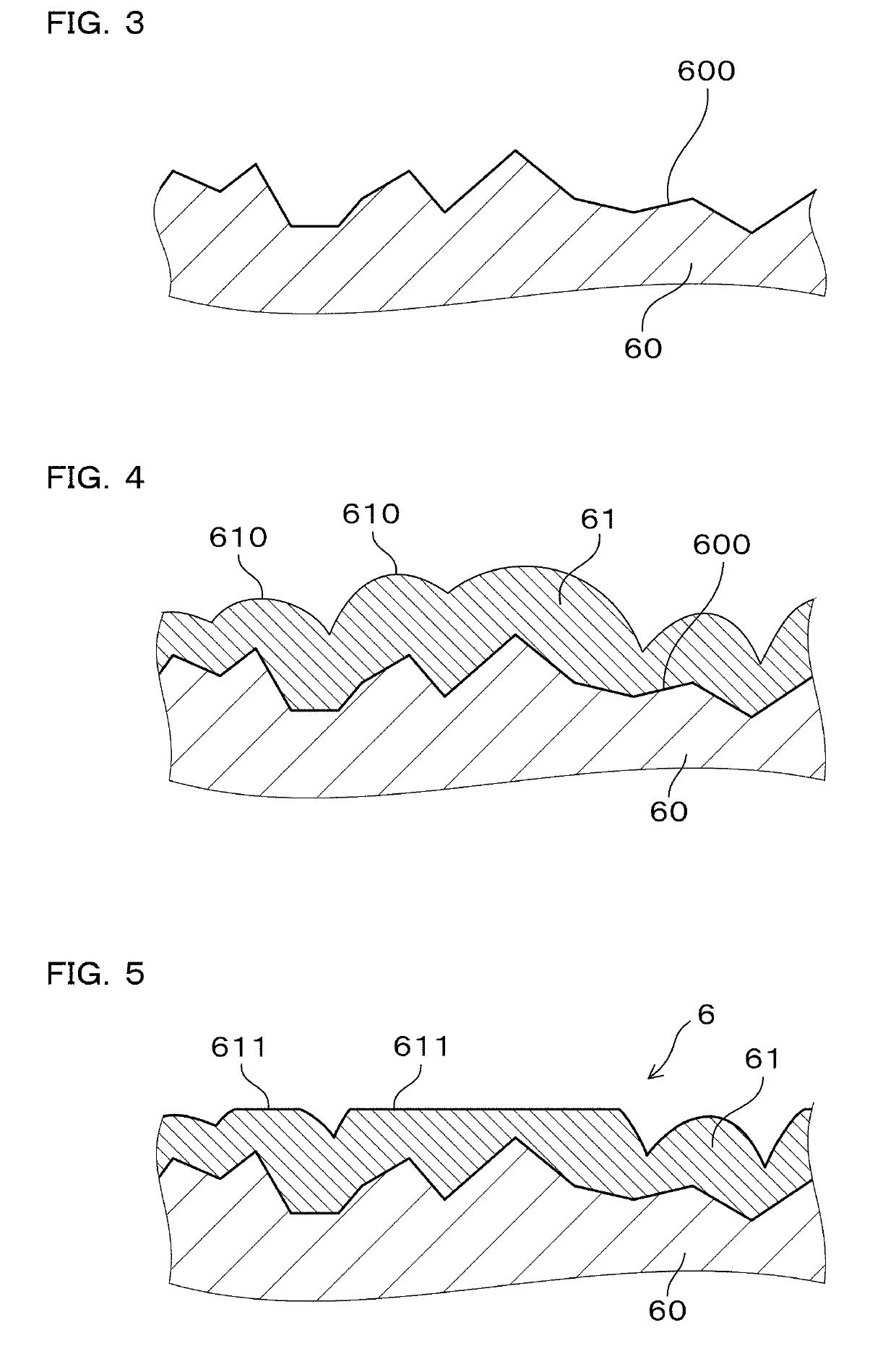
[0064]The current-collector metal foil 1 was prepared by passing, one or more times, the metal foil between a pair of roughening rolls 6 (refer to FIG. 5) prepared in advance, and performing a transfer process in which the contours of the roughening rolls 6 were transferred to the metal foil. Subsequently, the active-material-containing layer was formed on both surfaces of the current-collector metal foil 1, and thereby the current collector was prepared. The configuration and manufacturing method of the current-collector meta...

working example 1

[0065]The pair of roughening rolls 6 was prepared in advance based on the procedure below. First, shot blasting was performed on a pair of rolling rolls 60 using grit-blasting particles having a particle size of 40 μm, and thereby a surface 600 of both rolling rolls 60 was roughened as shown in FIG. 3. Next, a chrome-plating treatment was performed on the surface 600 of each rolling roll 60 to form a chrome-plated film 61. The chrome-plating treatment was performed in a Sargent's bath, containing 250 g / L of chromic anhydride and 2.5 g / L of sulfuric acid, and under the conditions of a temperature of 50° C. and an electric-current density of 30 A / dm2. The film thickness of the chrome-plated film 61 was set to 5 μm. As shown in FIG. 4, the chrome-plated film 61 preferentially adhered to the pointed portions of the surface 600, thereby forming numerous protruding parts 610 that are substantially spherically shaped.

[0066]Subsequently, the pair of rolling rolls 60, on which the chrome-pla...

working example 2

[0069]A pair of the roughening rolls 6 was prepared the same as in working example 1, excepting that the particle size of the grit-blasting particles and the rolling load in the process of flattening the peak parts of the chrome-plated film 61 were changed to the conditions shown in Table 1. Using the obtained roughening rolls 6, the contours of the roughening rolls 6 were transferred to a rolled-copper foil, having a thickness of 10 μm, based on conditions the same as in working example 1, and thereby metal foil E2 was obtained. The average Feret diameter Lave of the recessed parts 4 on metal foil E2 was 10.1 μm, and the depth of the deepest recessed part 4 was 2.0 μm.


PUM

PropertyMeasurementUnit
Feret diameteraaaaaaaaaa

Abstract

A current-collector metal foil has at least at least one roughened surface and numerous recessed parts are present on the roughened surface. Each recessed part has an edge part that surrounds a bottom-surface part and is raised above the bottom-surface part. The average Feret diameter Lave of the recessed parts is 0.5-50 μm. The current-collector metal foil is suitable for use, e.g., as an electrode current collector for a lithium-ion secondary battery, a sodium secondary battery, an electric double-layer capacitor, or a lithium-ion capacitor.

Description

CROSS-REFERENCE[0001]This application is the US national stage of International Patent Application No. PCT / JP2015 / 066085 filed on Jun. 3, 2015, which claims priority to Japanese Patent Application No. 2014-117769 filed on Jun. 6, 2014.TECHNICAL FIELD[0002]The present invention relates to a current-collector metal foil, a current collector, and a current-collector-metal-foil manufacturing method.BACKGROUND ART[0003]A current collector, which is used in devices such as secondary batteries and capacitors, is configured by affixing an electrode active material to the surface of a metal foil.[0004]For example, in a negative-electrode current collector of a lithium-ion secondary battery, a coating layer is formed by applying a slurry—which is prepared by mixing and dispersing a negative-electrode active material composed of a carbon powder, a binding agent, an electrically conductive agent, and the like into a solvent—to a metal foil, and subsequently removing the solvent by drying the co...

Claims


Application Information

Patent Timeline
Patent Type & Authority Patents(United States)
IPC IPC(8): H01M4/66C25D1/04C25D5/48C25D3/08H01M4/70H01M4/64C25D7/00B30B3/00H01G11/68H01G11/86C25D3/56H01M10/054H01M10/0525C25D7/06H01G11/70H01M4/02
CPCC25D1/04C25D5/48C25D7/00H01G11/86H01M4/70H01M10/0525B30B3/00C25D3/56C25D7/0614H01G11/70H01M4/661C25D3/08H01M4/64H01G11/68H01M10/054Y02E60/13H01M2004/021Y02E60/10B21D33/00H01M4/13
Inventor ASHIZAWA, KOICHIMOTOI, TETSUYAKOISHIKAWA, ATSUSHIFUNATO, YASUSHI
Owner FURUKAWA SKY ALUMINUM CORP
Why Eureka
Try Eureka