Rotor of small motor and its producing method

A manufacturing method and motor technology, applied in the manufacture of stator/rotor bodies, circuits, current collectors, etc., can solve problems such as inability to establish electrical connections, melting, difficult arc heat, etc.

Inactive Publication Date: 2002-10-16
MABUCHI MOTOR
View PDF0 Cites 3 Cited by
  • Summary
  • Abstract
  • Description
  • Claims
  • Application Information

AI Technical Summary

Problems solved by technology

[0005] However, when a material having a high melting point is used as an insulating layer for winding wires, it is difficult to be melted by the heat of the arc, causing a problem that a satisfactory electrical connection cannot be established

Method used


Image

  • Rotor of small motor and its producing method
  • Rotor of small motor and its producing method
  • Rotor of small motor and its producing method

Examples


Embodiment Construction

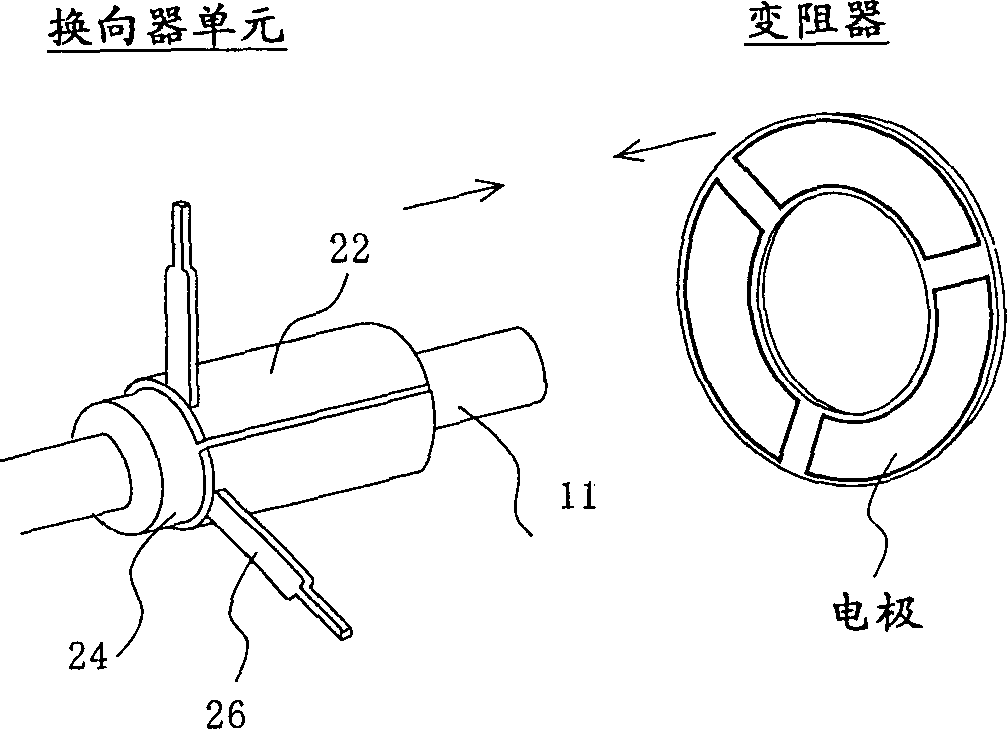
[0020] Figure 4 The structure of the rotor of a small electric motor to which the present invention can be applied is shown in . The structure on the stator side is not shown here, but any suitable conventional structure may be used with the rotor. For example, a small motor can be installed by inserting the illustrated rotor into a hollow cylindrical metal case with a bottom, relying on two magnets on its inner peripheral surface; installing the case cover to cover the opening of the metal case end. In this way, the two ends of the rotor shaft 11 are supported by two bearings, one bearing is arranged at the center of the bottom of the casing, and the other is arranged on the casing cover. Usually, a brush supported by the housing cover is also provided, and when the brush is in sliding contact with the commutator of the rotor, it is connected to the input terminal that enters the housing cover and protrudes inside to provide electrical energy from the outside .

[0021] ...


PUM


Abstract

The leading end of a wire to be wound fed from a coil winder is wound around one of commutator leg parts a prescribed number of turns and then wound around a corresponding salient pole. After that, it is similarly wound successively around other commutator leg parts and around other salient poles and, after it is wound around the same commutator leg part as the one around which the leading end of the wire was first wound, the wound wire is cut. Only the portions that will be wound around the commutator leg parts in synchronization with the feed of the wire to be wound from the coil winder are stripped of their insulating coat prior to being wound, and the wound portions of the commutator leg parts are welded.

Description

technical field [0001] The invention relates to a rotor of a small electric motor and a manufacturing method thereof. Such a rotor provides a satisfactory electrical connection between the winding ends and the commutator leads in an easily manipulable manner. Background technique [0002] The connection of commutator segments and winding ends according to the prior art is described with reference to FIG. 7 . Fig. 7 is a schematic perspective view of a commutator unit of a small motor. In the figure, numeral 11 represents the shaft of the rotor, 22 is a commutator segment; 24 is a commutator core; 26 is a commutator lead wire. Therefore, the commutator unit includes a commutator segment 22 and a commutator lead wire 26 provided on a commutator core 24 made of resin, and commutator lead wires 26 for connecting winding ends to each commutator lead wire at the commutator segment The ends of 22 are integrally formed therewith. Fig. 8 shows the shape of the commutator unit sho...

Claims


Application Information

Patent Timeline
Patent Type & Authority Applications(China)
IPC IPC(8): H01R39/32H02K13/00H02K13/04H02K13/10H02K15/02H02K23/66
CPCH01R39/32H02K13/04H02K13/105Y10T29/49011
Inventor 古屋建二芦川聪
Owner MABUCHI MOTOR
Why Eureka
Try Eureka