Carrier sensing method and RFID transceiver device using the same

a carrier sensing and rfid transceiver technology, applied in the direction of burglar alarm mechanical actuation, burglar alarm by hand-portable objects removal, etc., can solve the problems of undesirable transmission and reception of rfid transceiver devices with separate antennas, poor power, and inaccurate carrier sensing. , to achieve the effect of effective frequency utilization, accurate carrier sensing, and efficient application

Inactive Publication Date: 2006-10-12
FUJITSU LTD
View PDF8 Cites 8 Cited by
  • Summary
  • Abstract
  • Description
  • Claims
  • Application Information

AI Technical Summary

Benefits of technology

[0033] According to the present invention, accurate carrier sensing can be achieved. Consequently, efficient application of an RFID system can thereby be achieved and effective frequency utilization becomes possible.

Problems solved by technology

While the RFID transceiver device executes communication with the IC tag in this way, it is undesirable that communication using a specified carrier frequency should be performed exclusively by a specified RFID transceiver device.
In contrast, since the response transmission from the IC tag is performed by back scattering, its power is very weak in comparison with the power of the electromagnetic wave transmitted by the RFID transceiver device.
Also, providing the RFID transceiver device with separate antennas for transmission and reception is undesirable from the point of view of cost and size.
There is therefore the problem that, when carrier sensing is performed, if the frequency offset Δf from the other RFID transceiver device is close to “0”, carrier sensing cannot be accurately performed due to the effect of DC component removal.

Method used


Image

  • Carrier sensing method and RFID transceiver device using the same
  • Carrier sensing method and RFID transceiver device using the same
  • Carrier sensing method and RFID transceiver device using the same

Examples


Embodiment Construction

[0045] Embodiments of the present invention are described below with reference to the drawings. It should be noted that the embodiments are given merely to facilitate understanding of the present invention and the technical scope of the present invention is not intended to be restricted thereto.

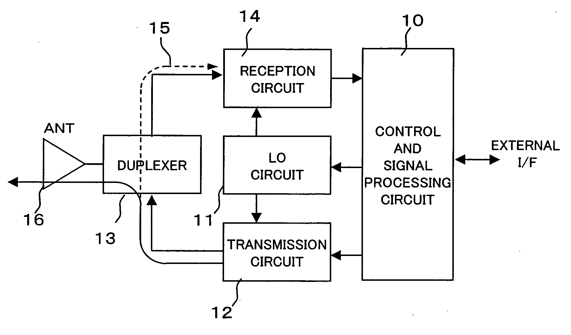
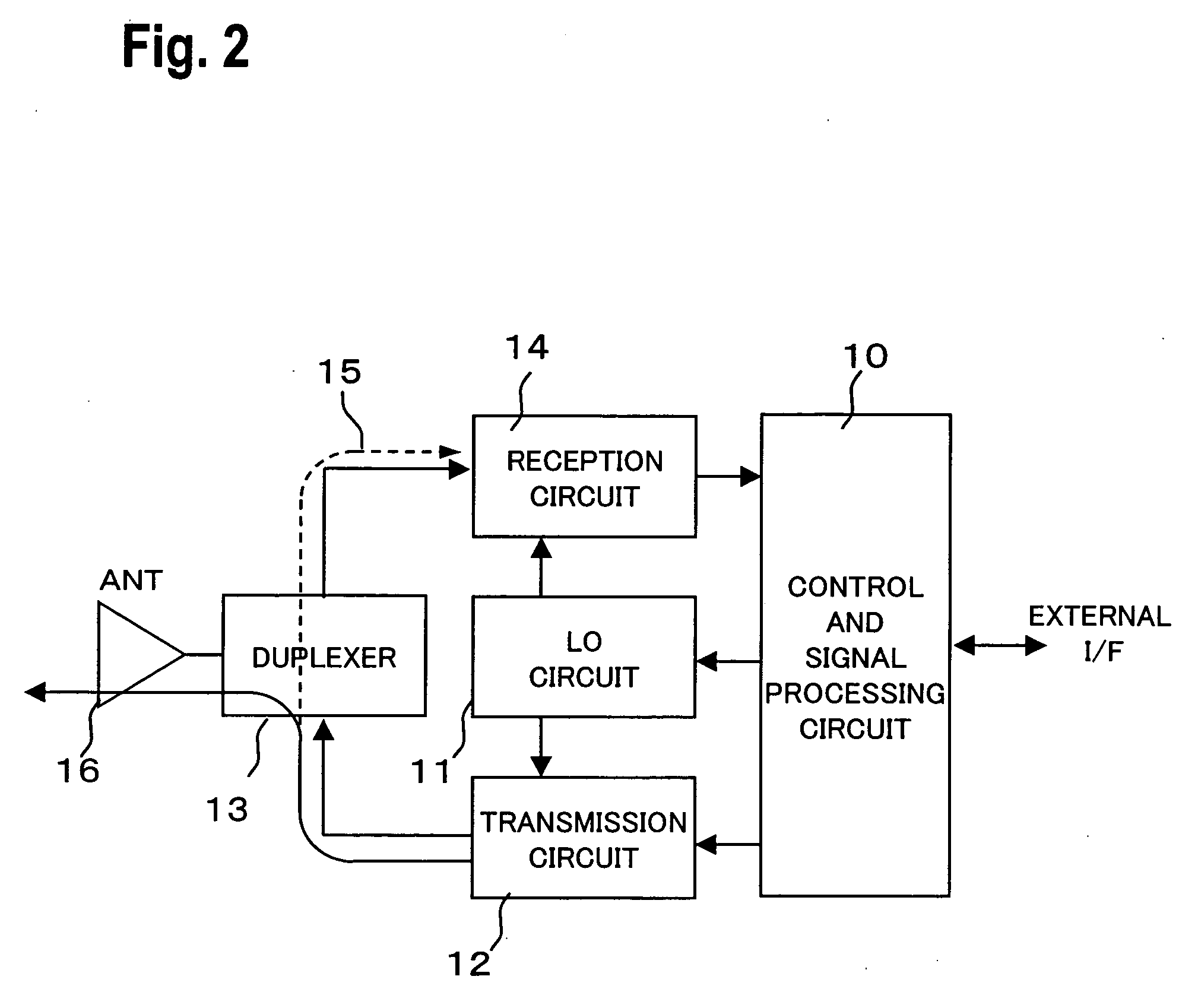
[0046]FIG. 6 is a block diagram of a first embodiment of an RFID transceiver device according to the present invention.

[0047] A feature of the present invention is that, when performing carrier sensing, a demodulation local oscillation frequency (fL0+fs) that is shifted in frequency by a prescribed frequency fs with respect to the reference local oscillation frequency fL0 that is employed when ordinary communication with an IC tag is performed.

[0048]FIG. 7 is a block diagram of an example of the block diagram of a local oscillation signal oscillator 11 for implementing the above feature.

[0049] A reference signal source 110 outputs a reference oscillation frequency fREF of high precision. ...


PUM


Abstract

An RFID transceiver device is proposed capable of carrier sensing even when the difference with respect to the carrier frequency employed by the other system is close to “0”. The device includes a control and signal processing circuit; a local oscillation circuit that generates a local oscillation signal of frequency that is specified by said control and signal processing circuit; and a reception circuit that demodulates the reception signal using the local oscillation signal frequency that is output from said local oscillation circuit; wherein the control and signal processing circuit performs control so as to output, to the local oscillation circuit, a local oscillation signal of a reference frequency in the case of ordinary communication, and output, to the local oscillation circuit, a local oscillation signal shifted by a prescribed frequency with respect to said reference frequency in the case of carrier sensing, as a local oscillation signal for demodulating the reception signal in the reception circuit.

Description

CROSS-REFERENCE TO RELATED APPLICATIONS [0001] This application is based upon and claims the benefit of priority from the prior Japanese Patent Application No. 2005-109546, filed on Apr. 6, 2005, the entire contents of which are incorporated herein by reference. BACKGROUND OF THE INVENTION [0002] 1. Field of the Invention [0003] The present invention relates to a carrier sensing method and RFID transceiver device using the same. [0004] 2. Description of the Related Art [0005] RFID (radio frequency identification) systems are employed in various applications. In such systems, a carrier signal is transmitted from an interrogator to a transponder, the carrier signal that is reflected (back-scattered) from the transponder is received, and the modulation signal component that is contained in the back-scattered carrier signal is processed as information data from the transponder. [0006] The interrogator is an RFID transceiver device called a reader / writer (RW). The transponder may be of v...

Claims


Application Information

Patent Timeline
Patent Type & Authority Applications(United States)
IPC IPC(8): H04B1/26
CPCG06K19/07G06K7/10069
Inventor NINOMIYA, TERUHISATANAKA, YOSHINORI
Owner FUJITSU LTD
Why Eureka
Try Eureka