Surgical instrument seal assembly

a surgical instrument and seal technology, applied in the field of medical devices, can solve the problems of affecting the sealing effect of the valve, affecting the safety of the patient, and the elastomeric material of the valve seal can be damaged, and achieve the effect of simple production and low cos

Inactive Publication Date: 2006-10-12
DENNIS WILLIAM G +1
View PDF33 Cites 40 Cited by
  • Summary
  • Abstract
  • Description
  • Claims
  • Application Information

AI Technical Summary

Benefits of technology

[0007] Therefore, there is a need for a surgical instrument sealing assembly that provides protection for the valve seal during contact with the instrument, especially during off axis insertion of the instrument, that is inexpensive and simple to produce.
[0008] It is accordingly an object of the present invention to provide a surgical instrument seal assembly having a valve seal that can withstand impact from a surgical instrument.
[0010] It is another object of the present invention to provide a seal assembly that is simple and easy to produce.
[0011] Accordingly, a surgical instrument seal assembly is provided as described in the description of the exemplary embodiments. The present invention provides a unitary valve seal that includes an armor reinforcement that is unitarily formed with the elastomeric seal material and protects the integrity of the elastomeric seal material during insertion of the surgical instrument. Further, the valve seal is configured to allow some off-axis movement of a valve opening in the valve seal while a mounting portion of the valve seal itself remains rigidly mounted within its housing. Thus, while the upper portion of the valve seal may be incapable of lateral movement, the valve opening itself can shift a small amount to accommodate an off-axis instrument insertion.

Problems solved by technology

However, certain problems have been identified in conjunction with use and operation of conventional devices.
Initially, the elastomeric material of the valve seal can be damaged by contact with the surgical instrument upon insertion.
These approaches have been generally costly and complex.
Another problem with conventional devices has been the inability of the valve opening to align with the instrument if the instrument is inserted “off axis,” i.e., out of alignment with the throughbore in the valve seal.
These solutions have required additional material and can be expensive and complex.

Method used


Image

  • Surgical instrument seal assembly
  • Surgical instrument seal assembly
  • Surgical instrument seal assembly

Examples


Embodiment Construction

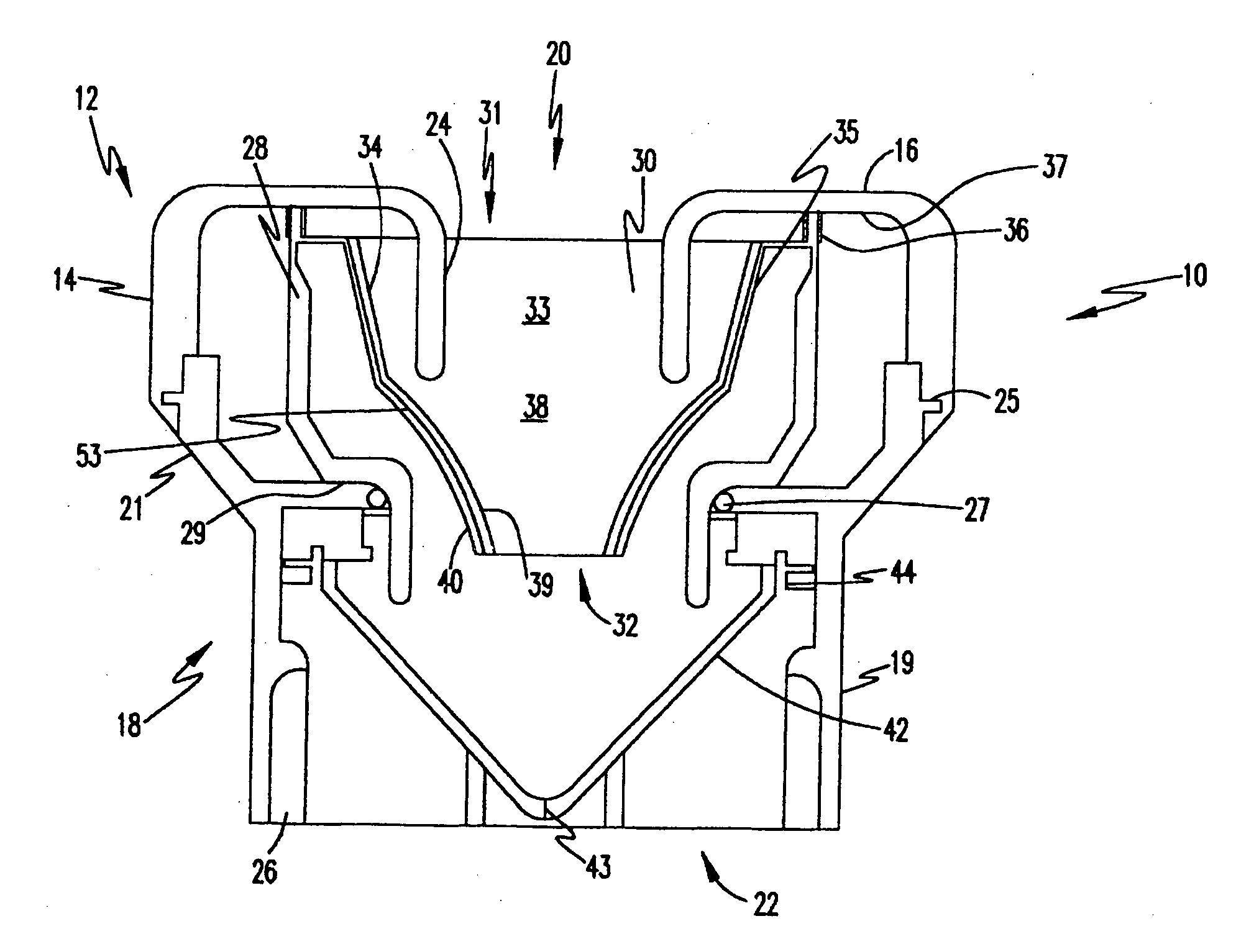
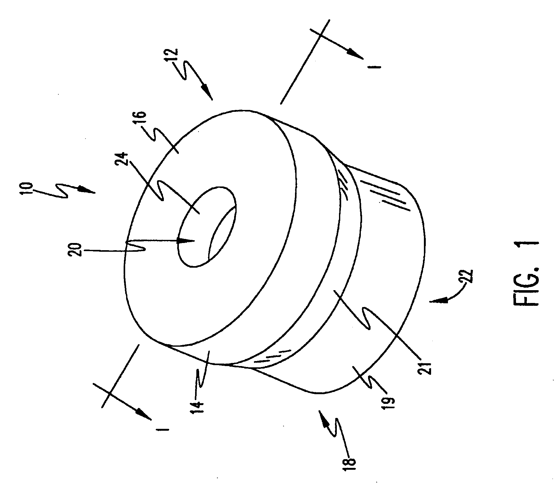
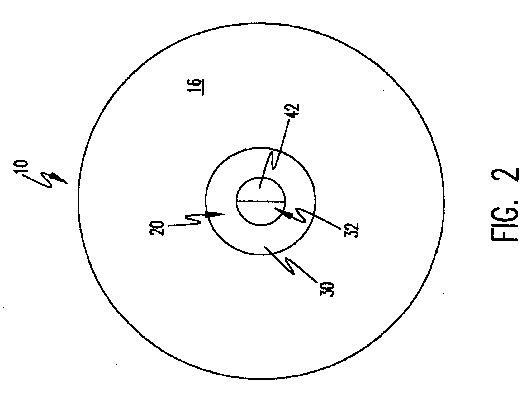
[0037] With reference to the drawings, wherein like numerals have been used to represent like features, and, more particularly to FIG. 1, a surgical instrument valve seal assembly 10 is illustrated and includes an upper body portion 12 and a lower body portion 18. The upper body portion 12 is generally cylindrical and includes a washer-shaped upper surface 16 integrally formed with a generally cylindrical sidewall 14. A throughbore 20 is provided at the center of the upper surface 16 with the throughbore 20 extending completely through the seal assembly 10. A generally cylindrical protector wall member 24 is integrally formed with upper surface 16 at the throughbore 20 to project inwardly into the interior of the upper body portion 12 to both strengthen the structure and to guide the surgical instrument into the throughbore 20.

[0038] The lower body portion 18 includes a generally cylindrical wall 19 projecting below the upper body portion 12. A tapered transition wall 21 is dispose...


PUM


Abstract

A surgical instrument valve assembly is provided with a valve seal where the upper portion of the valve seal is rigidly mounted to the body of the valve assembly. The lower portion of the valve seal is configured to allow some radial movement while the upper portion of the valve seal remains rigidly mounted within the valve assembly. The valve seal may be provided with stay that prevents the valve seal from inverting when an instrument is withdrawn from the valve assembly.

Description

[0001] This application is a continuation of and claims the benefit of co-pending application Ser. No. 09 / 885,856, filed Jun. 20, 2001, which stands allowed and which is a continuation of and claims benefit of application Ser. No. 09 / 434,608, filed Nov. 5, 1999, now U.S. Pat. No. 6,258,065; which claims benefit of Provisional Application No. 60 / 126,356 filed on Mar. 26, 1999, which are incorporated herein by reference in their entireties.FIELD OF THE INVENTION [0002] The present invention relates broadly to medical devices used during surgical procedures and, more particularly to a surgical instrument seal assembly for selective mounting to a cannula for the insertion of a surgical instrument therethrough while maintaining a fluid seal around the instrument. BACKGROUND OF THE INVENTION [0003] In certain types of surgery, a cannula is used to provide a passageway into a body cavity through which surgical instruments may be passed. Cannulas are typically elongate rod-like members havi...

Claims


Application Information

Patent Timeline
Patent Type & Authority Applications(United States)
IPC IPC(8): A61M5/178A61B17/34
CPCA61B2017/3464A61B17/3462
Inventor DENNIS, WILLIAM G.PROSEK, MICHAEL E.
Owner DENNIS WILLIAM G
Why Eureka
Try Eureka