Night vision aiming sight with two eyepieces

a technology of aiming sight and eyepiece, which is applied in the field of weapons aiming sights, can solve the problems of he may become a potential target, the image provided by the camera is of course lost, and the light level is too low

Active Publication Date: 2006-10-19
THALES SA
View PDF8 Cites 20 Cited by
  • Summary
  • Abstract
  • Description
  • Claims
  • Application Information

AI Technical Summary

Benefits of technology

[0011] Advantageously, the first optical channel comprises at least one image transfer optic for the intensified image coming from the image intensifier, a semireflecting plate, a first relay optic, a first eyepiece, the final image from the first eyepiece being substantially collimated and the exit pupil of said first optical channel being substantially coincident with the entrance pupil of the objective of the camera when the sight is mounted on the weapon. Furthermore, the seco...

Problems solved by technology

When a soldier is aiming his weapon, he may become a potential target.
In this case, the image provided by the camera is of course lost, the ...

Method used


Image

  • Night vision aiming sight with two eyepieces
  • Night vision aiming sight with two eyepieces
  • Night vision aiming sight with two eyepieces

Examples


Embodiment Construction

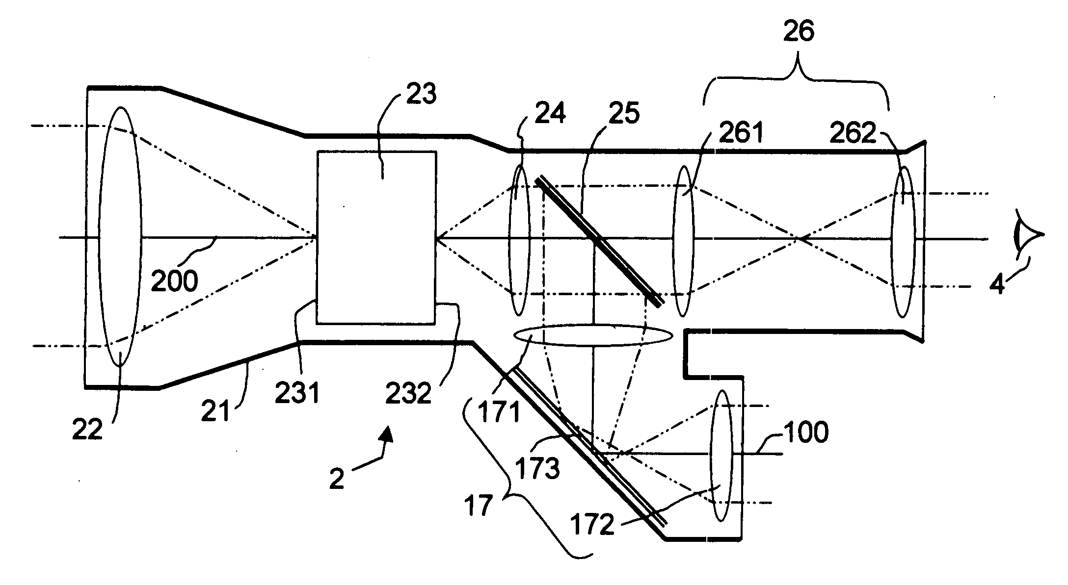
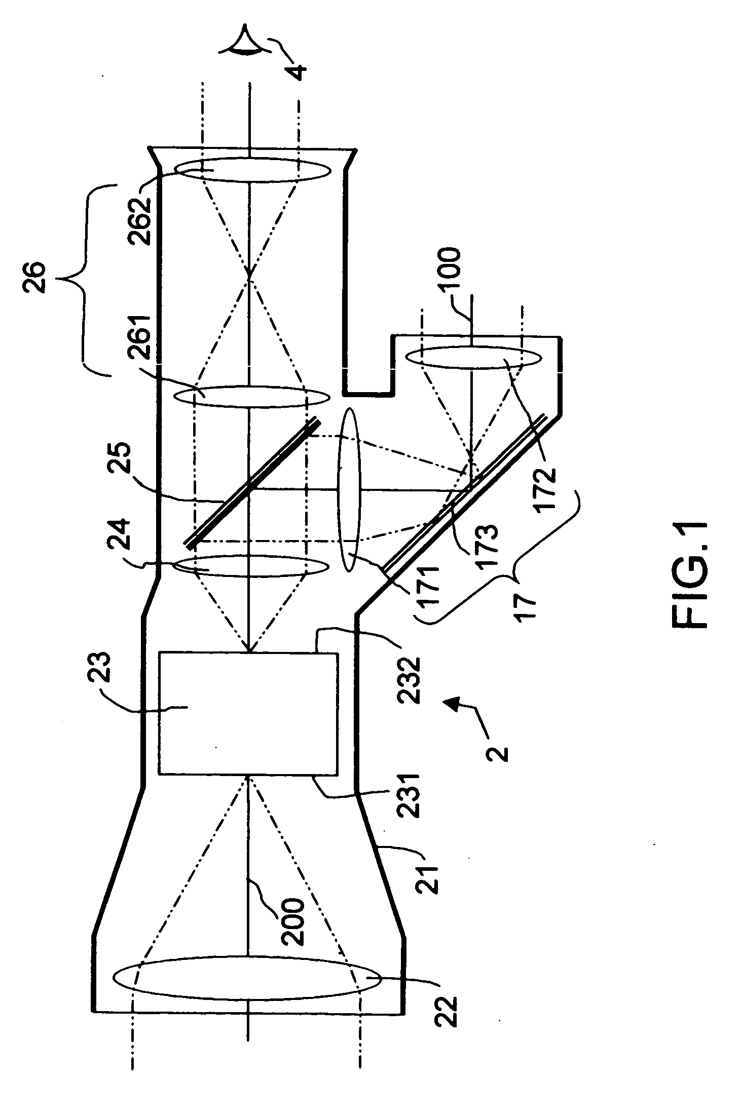
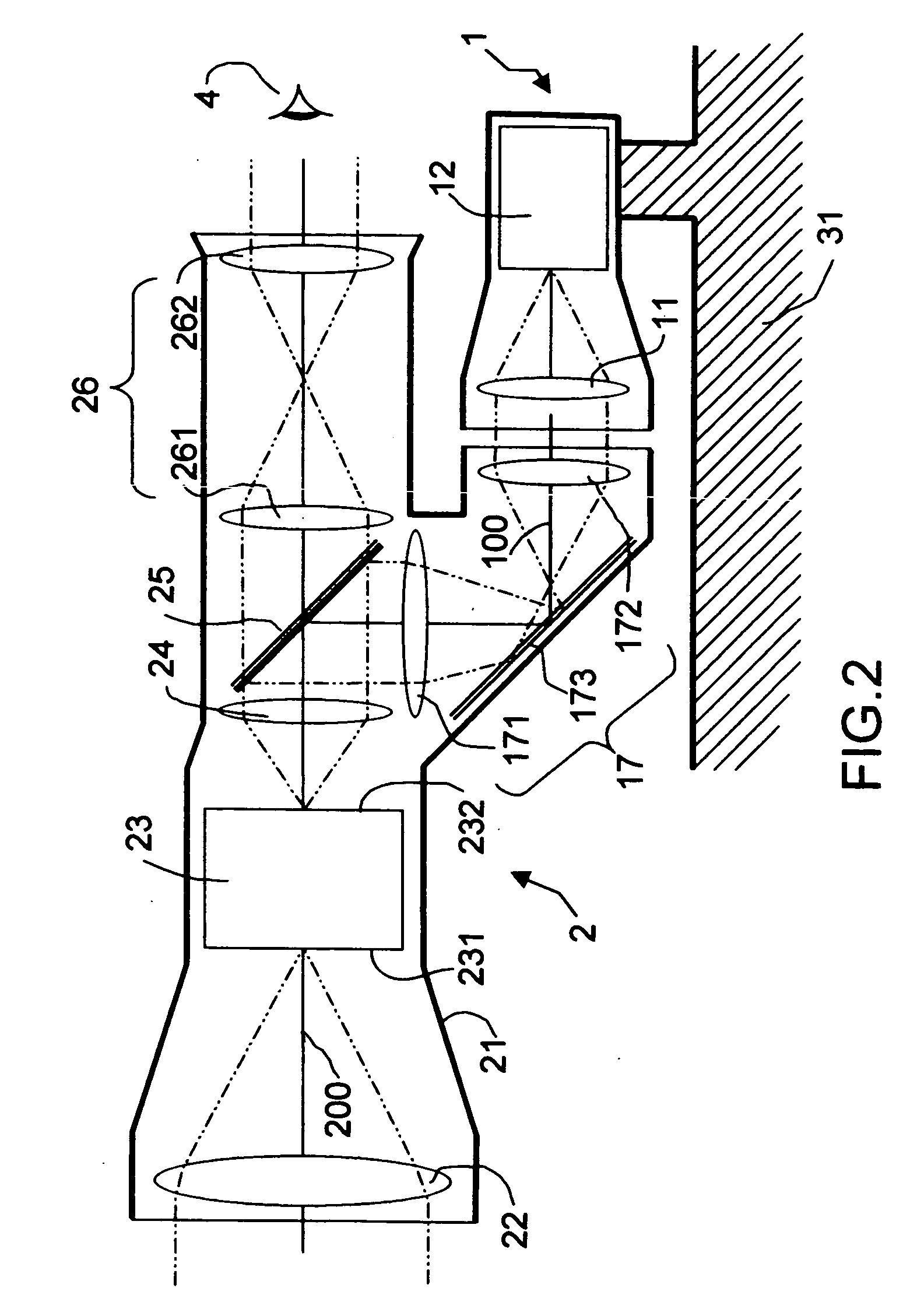
[0020]FIG. 1 shows a schematic view of the night vision aiming sight 2 according to the invention. The path of the light rays coming from an object point located at infinity on the optical axis of the sight is indicated by dotted lines, thus making it possible to follow the various focusing and collimating operations carried out on the light rays through the various optics of the aiming sight.

[0021] The latter comprises an objective 22 that forms an image of the external scenery on the entrance window 231 of an image intensifier device 23. This gives, on its exit window 232, an inverted intensified image. Two optical channels placed behind the intensifier 23 each give a collimated image. These two optical channels have a common part formed from an image transfer optic 24 and a semireflecting plate 25.

[0022] The transfer optic 24 provides a first image of the intensified image coming from the intensifier 23. In FIG. 1, the semireflecting plate 25 reflects part of said image into a ...


PUM


Abstract

The field of the invention is that of weapon aiming sights having a light intensifier. To make certain firing modes safe, a weapon may be provided with a camera allowing a soldier to take aim while remaining protected. The proposed invention allows this function to be fulfilled at night. For this purpose, a night vision aiming sight with a light intensifier comprising two optical channels is fitted onto the weapon. The first optical channel provides the camera placed on the weapon with an intensified image. The second optical channel provides the firer with a directly observable intensified image. In a variant, the aiming sight also includes a display that supplies the soldier with additional information superimposed on the intensified images.

Description

BACKGROUND OF THE INVENTION [0001] 1. Field of the Invention [0002] The field of the invention is that of weapon aiming sights having a light intensifier. [0003] 2. Description of the Prior Art [0004] It is of paramount importance for a soldier to maintain very good mobility in all mission situations and particularly when he is moving around in an urban environment. When a soldier is aiming his weapon, he may become a potential target. To obviate this drawback, a video camera is placed on the barrel of the weapon, this camera being, for example of the CCD (charge coupled device) sensor type. This camera is coupled either to a helmet sight positioned on the soldier's helmet, or to an imager positioned for example on his wrist. This device allows the soldier to take a shifted sight of the target and consequently allows him to fire while remaining protected. However, the firing configuration most often used nevertheless remains that in which the soldier takes direct aim of the target w...

Claims


Application Information

Patent Timeline
IPC IPC(8): F41G1/38F41G1/32G02B23/12
CPCG02B23/12F41G1/32
Inventor NARCY, GABRIELESPIE, JEAN-LUC
Owner THALES SA
Why Eureka
Try Eureka