Twin belt mule drive

a mule drive and belt technology, applied in the field of belt drive systems, can solve the problems of limited power a mule drive can transmit, thick and/or strong belts may not be sufficiently flexible to use in mule drives, and it is difficult to twist and change the orientation of such a belt, so as to achieve the effect of increasing the belt life and increasing the power

Inactive Publication Date: 2006-10-19
DEERE & CO
View PDF27 Cites 3 Cited by
  • Summary
  • Abstract
  • Description
  • Claims
  • Application Information

AI Technical Summary

Benefits of technology

[0006] The present invention provides a simplified and improved twin belt mule drive for a mower deck with three rotary cutting blades. The twin belt mule drive transmits less load through each of the two belts, leading to increased belt life. The twin belt mule drive can transmit higher power to drive wider mower decks. In the present invention, all three rotary cutting blades are driven by two belts. The drive shaft or PTO from the engine has a pair of drive sheaves. The two belts are twisted from a vertical to a horizontal plane by two pairs of guide sheaves. Each of the two belts engages at least one of the driven sheaves that is not engaged by the other belt.

Problems solved by technology

The power a mule drive can transmit may be limited by the thickness and / or strength of the belt.
However, very thick and / or strong belts may not be sufficiently flexible to use in a mule drive.
It can be difficult to twist and change the orientation of such a belt.
As a result, the application of mule drives is limited.
The third belt adds to the cost and complexity of this mule drive.
Additionally, the configuration of idler pulleys at various outboard locations relative to the drive sheave also increases the cost and complexity of this mule drive.

Method used


Image

  • Twin belt mule drive
  • Twin belt mule drive
  • Twin belt mule drive

Examples


Embodiment Construction

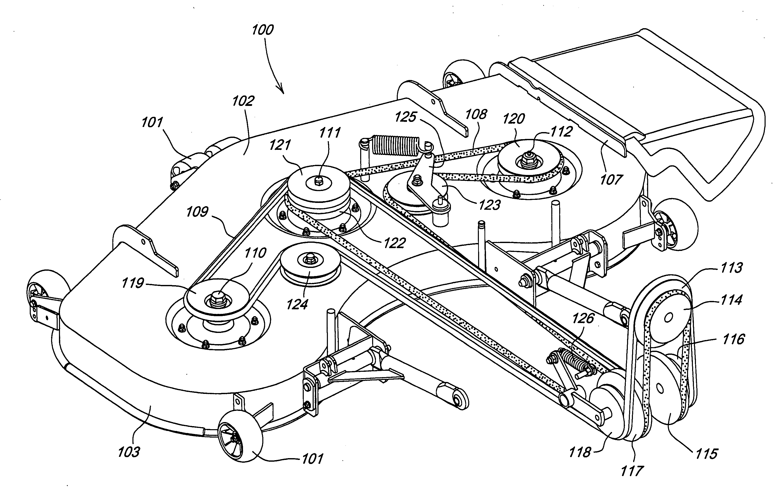
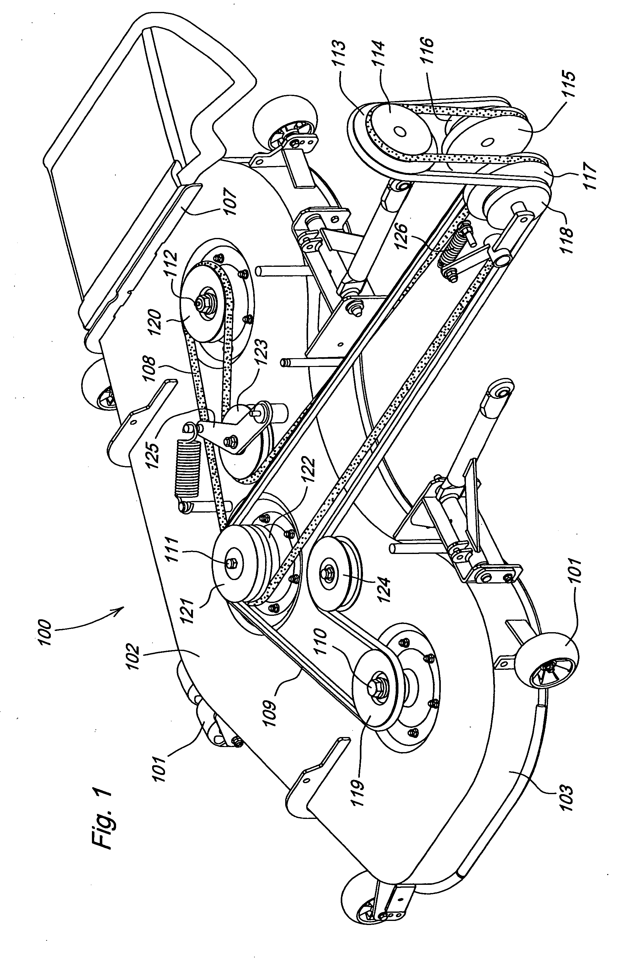
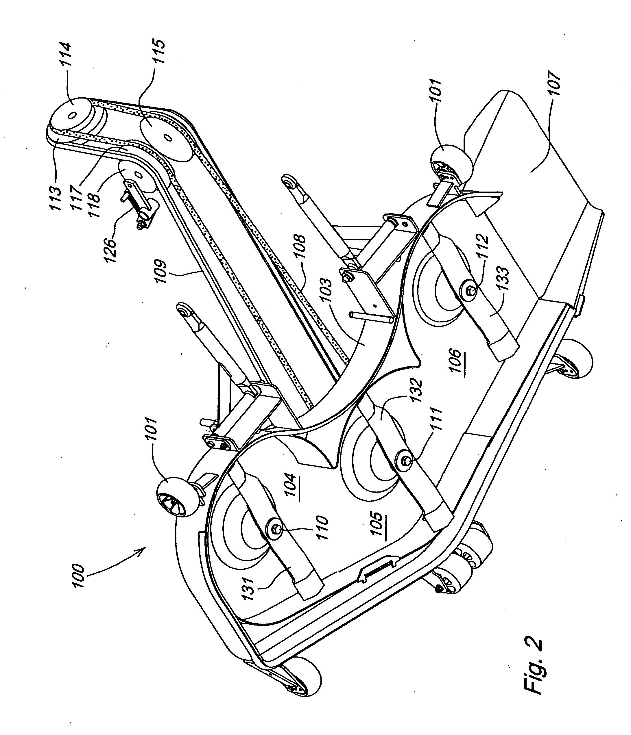
[0009]FIGS. 1 and 2 show a first embodiment of the invention, in which a twin belt mule drive is used on mower deck 100 to drive three rotary cutting blades 131, 132, 133. Mower deck 100 may be removably mounted to or suspended from the frame of a tractor or similar vehicle at or near the front or middle of the vehicle. The mower deck may have anti-scalp wheels 101 attached to its outer perimeter. The vehicle may have an internal combustion engine or other power source, a transmission, and one or more ground engaging wheels. The engine may provide at least about 15 horsepower to a horizontal drive shaft or PTO.

[0010] In one embodiment, mower deck 100 may have a top surface 102, downwardly depending sides 103, and an overall width of at least about 48 inches. The twin belt drive of the present invention is capable of driving significantly wider mower decks. Blades 131-133 under the mower deck may be housed in adjacent and interconnected cutting chambers 104-106. The middle cutting c...


PUM


Abstract

A twin belt mule drive for a mower deck has a pair of belts that transmit power from a drive shaft or PTO to driven sheaves for three rotary cutting blades. The drive shaft or PTO has two drive sheaves. The belts are twisted by two pairs of guide sheaves on horizontal shafts below the drive sheaves. The first belt transmits power to at least one of the driven sheaves, and the second belt transmits power to at least one other driven sheave that is not engaged by the first belt.

Description

FIELD OF THE INVENTION [0001] The present invention relates generally to grass and vegetation mowing machines, and more specifically to belt drive systems that transmit power from an engine to rotary cutting blades under a mower deck. BACKGROUND OF THE INVENTION [0002] Belt drive systems are used on grass and vegetation mowing machines for transmitting power from an engine drive shaft or PTO to rotary cutting blades under a mower deck. Belt drive systems commonly known as mule drives are used to transmit power from a horizontally oriented drive shaft or PTO to vertically oriented spindles. Mule drives for mower decks include one or more guide sheaves that twist the belt to change its orientation from vertical to horizontal. An example of a mule drive for a mower deck is shown in U.S. Pat. No. 4,325,210. [0003] The power a mule drive can transmit may be limited by the thickness and / or strength of the belt. However, very thick and / or strong belts may not be sufficiently flexible to us...

Claims


Application Information

Patent Timeline
Patent Type & Authority Applications(United States)
IPC IPC(8): A01D69/10
CPCA01D34/76
Inventor WOUW, ROB VAN
Owner DEERE & CO
Why Eureka
Try Eureka