Variable valve timing control apparatus of internal combustion engine
- Summary
- Abstract
- Description
- Claims
- Application Information
AI Technical Summary
Benefits of technology
Problems solved by technology
Method used
Image
Examples
Embodiment Construction
[0027] The present invention will be explained below with reference to the drawings. In the following description, the terms “front” and “rear” are used for purposes of locating one element relative to another and are not to be construed as limiting terms. Further, although each of the variable valve timing control apparatus of the embodiments below is applied to control of open and closing timing of an intake valve for an internal combustion engine, it can also be applied to control of open and closing timing of an exhaust valve.
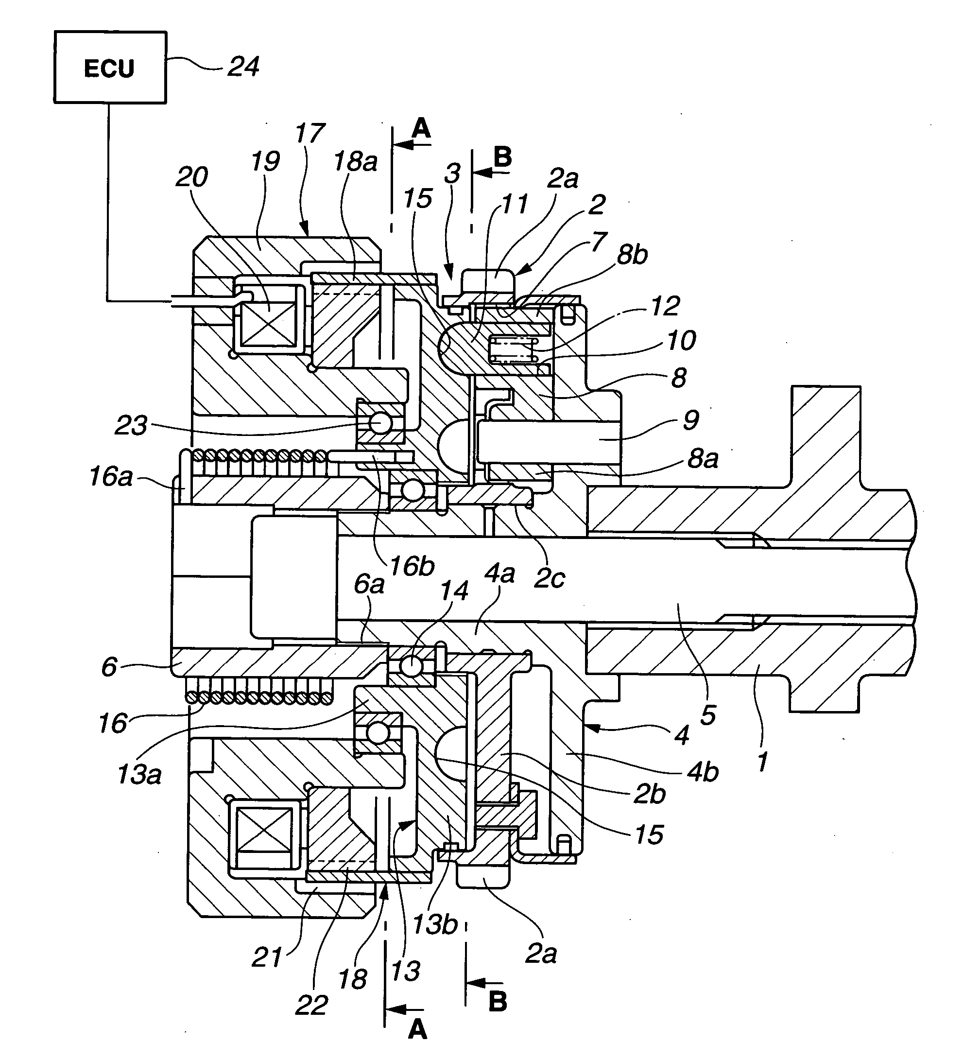
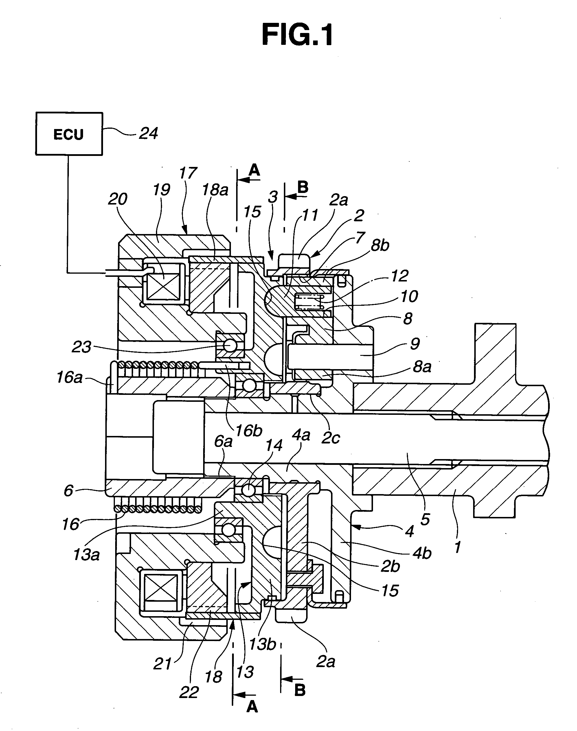
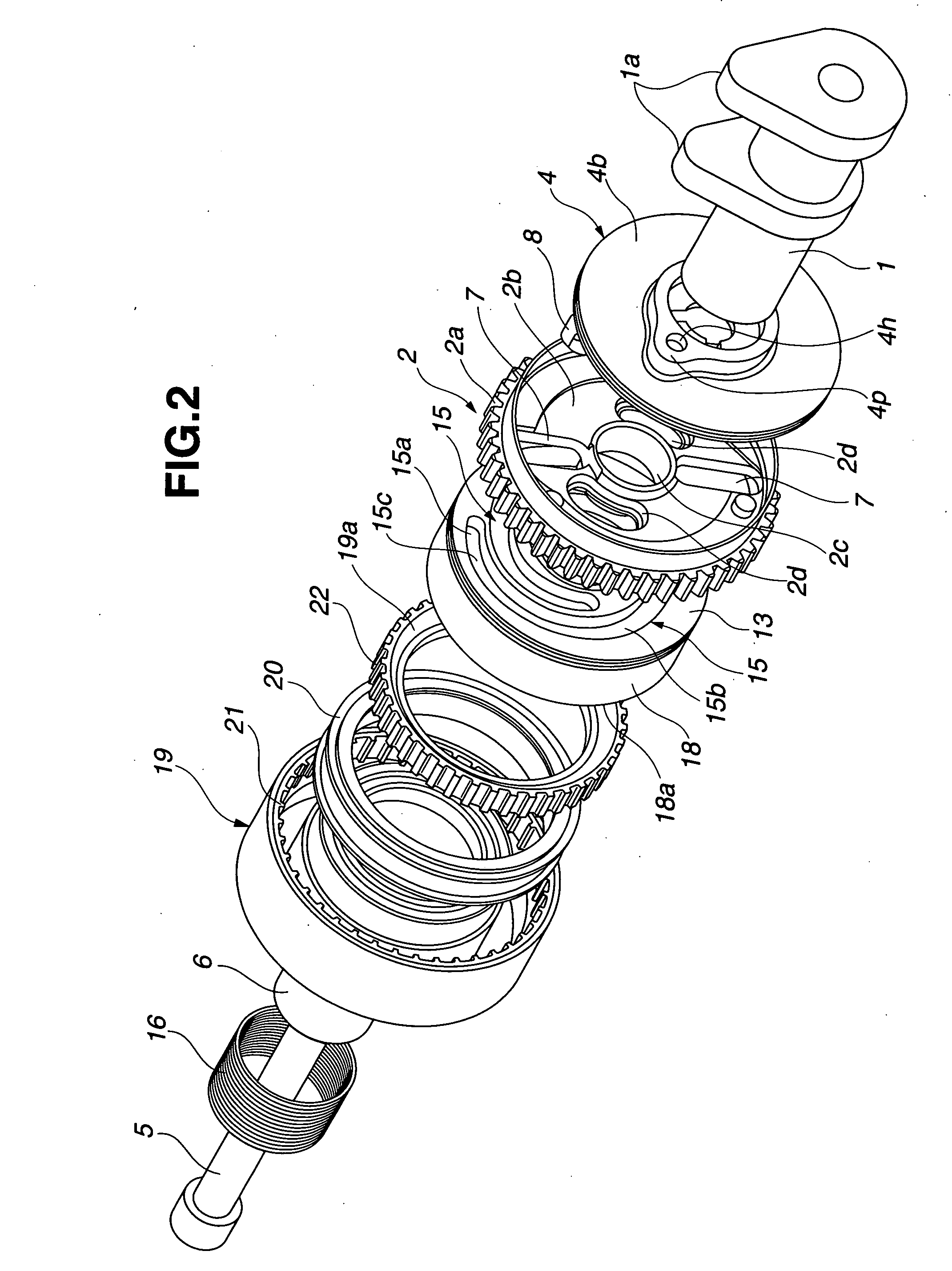
[0028] Firstly, a first embodiment of the present invention will be explained with reference to FIGS. 1 to 7. A variable valve timing control apparatus of the first embodiment includes a camshaft 1 rotatably supported on a cylinder head (not shown), a timing sprocket 2 (as a drive rotary member) rotatably disposed at front side of camshaft 1, and a relative angular phase control mechanism (simply, a phase converter or a phase-change mechanism) 3 disposed i...
PUM
 Abstract
Description
Claims
Application Information
 - R&D
- Intellectual Property
- Life Sciences
- Materials
- Tech Scout
- Unparalleled Data Quality
- Higher Quality Content
- 60% Fewer Hallucinations
Browse by: Latest US Patents, China's latest patents, Technical Efficacy Thesaurus, Application Domain, Technology Topic, Popular Technical Reports.
© 2025 PatSnap. All rights reserved.Legal|Privacy policy|Modern Slavery Act Transparency Statement|Sitemap|About US| Contact US: help@patsnap.com


