
Regeneration of adsorption media within electrical purification apparatuses

a technology of purification apparatus and adsorption media, which is applied in the direction of lighting and heating apparatus, membranes, separation processes, etc., can solve the problem that the regeneration of resins is not effected by such sporadic cleaning regimens, and the effect of little, if any,

Inactive Publication Date: 2006-10-19
SIEMENS WATER TECH HLDG CORP
View PDF99 Cites 35 Cited by
  • Summary
  • Abstract
  • Description
  • Claims
  • Application Information

AI Technical Summary

Benefits of technology

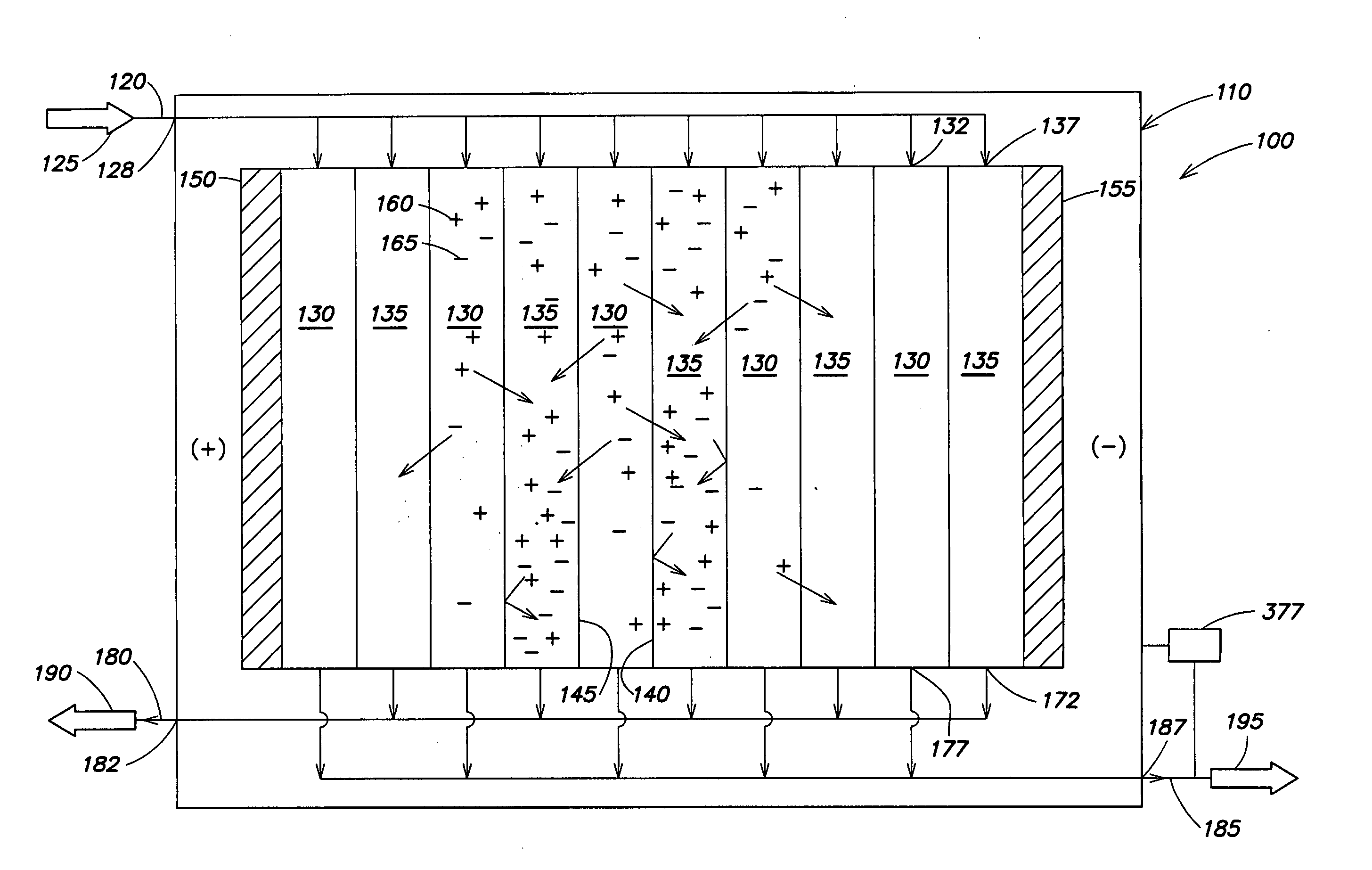
[0004] The present disclosure generally relates to methods, systems, and devices for electrically purifying liquids containing species such as minerals, salts, ions, organics, and the like. The subject matter of this invention involves, in some cases, interrelated products, alternative solutions to a particular problem, and / or a plurality of different uses of one or more systems and / or articles.

Problems solved by technology

Conventionally, cleaning is performed only when the device has become clogged or unusable for achieving desired water purity, for example, due to fouling of the resins.
However, little, if any, regeneration of the resins is effected by such sporadic cleaning regimens.

Method used


Image

  • Regeneration of adsorption media within electrical purification apparatuses
  • Regeneration of adsorption media within electrical purification apparatuses
  • Regeneration of adsorption media within electrical purification apparatuses

Examples


example 1

[0101] This example illustrates the use of an electrodeionization device, in accordance with one embodiment of the invention. An electrical purification apparatus, including an electrodeionization device, was assembled, having a configuration similar to that shown in FIG. 3. In this system, the electrodeionization device was set up to provide polarity reversal and to run essentially continuously. The electrodeionization device included 20 cell pairs (i.e., 20 pairs of adjacent concentrating and diluting compartments), with each cell having a thickness of about 0.23 cm (about 0.09 in), and a flow path length within each cell of about 66 cm (about 26 in). In each cell, liquid flows from the top of the cell, to the bottom of the cell; then, the liquid entered the next cell, at the bottom, and flows to the top. The operating conditions of the electrodeionization device were selected such that the device was able to produce a purified liquid at a product flow rate of about 2.27 l / min (ab...

example 2

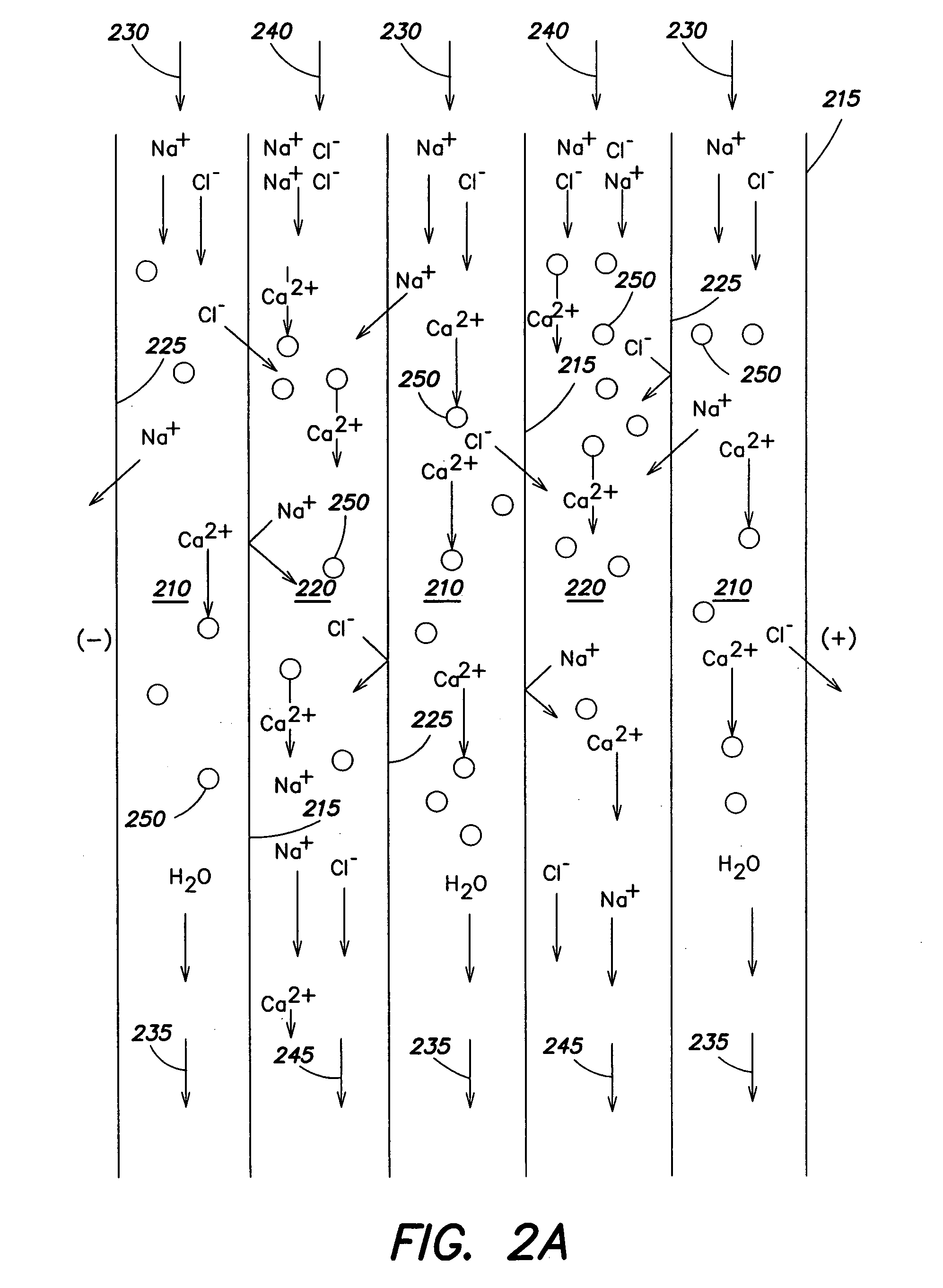
[0106]FIG. 7 illustrates another experiment using a similar electrical purification apparatus as the one described in Example 1 and illustrated in FIG. 3, but, compared with the operating conditions of Example 1, in the present example, the system was operated with a somewhat lower concentration of Ca2+in the feed stream, about 16 ppm. The remaining ion concentrations were as follows: 100 ppm HCO3−, 70 ppm Mg2+, 160 ppm Na+, 50 ppm SO42−, and 96 ppm Cl−. The regeneration solution was 10 wt % NaCl, applied for 30 minutes to the resin every six hours. An experiment was performed for about 6 hours, and some of the data from one cycle of the experiment are presented in FIG. 7.

[0107] It was observed that, while the concentration of Ca2+in the feed remained constant during the experiment at about 16 ppm, the electrical purification apparatus was able to remove nearly all Ca2+from the feed stream, resulting in a product (“dilute”) stream, generally having a negligible concentration of Ca2...

example 3

[0109] This example illustrates the essentially continuous use of certain electrical purification apparatuses, according to various embodiments of the invention. An electrical purification apparatus was assembled, similar to the one illustrated in FIG. 3. The electrical purification apparatus included an electrodeionization device, which included five pairs of cells (i.e., five pairs of concentrating and diluting compartments). Each of the cells had a thickness of about 0.23 cm (about 0.09 in), and a flow path length of about 38 cm (about 15 in). The operating conditions of the electrodeionization device were set such that the device was able to produce a product flow rate of about 0.4 l / m. The voltage applied to the electrodeionization device during operation was about 3 V / cell pair (about 30 V total). The feed stream introduced into the electrical purification apparatus was hard water including about 200 ppm of TDS, including a hardness of about 17 mg / l of CaCO3 (about 1 gr / gal ha...


PUM

PropertyMeasurementUnit
concentrationsaaaaaaaaaa

Abstract

The present disclosure generally relates to methods, systems, and devices for electrically purifying liquids containing species such as minerals, salts, ions, organics, and the like. One aspect of the invention provides an electrical purification apparatus, including an electrodeionization device. The electrodeionization device may be run in any suitable fashion, for example, continuously or essentially continuously, intermittently, upon demand, with periodic reversals of polarity. In another aspect, methods of regenerating media within an electrical purification device are provided, for example, exposing the media to one or more eluting solutions, and / or selectively desorbing ions, organics, and / or other species from the media by exposing the media to certain eluting conditions. In yet another aspect, methods of selectively removing one or more ions, organics, and / or other species from a liquid to be purified are provided, by selective removal of one or more ions, or organics, and the like from solution that can easily precipitate, and / or cause scaling or fouling to occur. In still another aspect, the invention provides a method of treating a solution containing ions, organics, and / or other species using an electrical purification apparatus in a continuous or semi-continuous fashion, while also performing regeneration of media contained within the apparatus.

Description

FIELD OF INVENTION [0001] The present invention generally relates to methods, systems, and devices for purifying liquids via electrical purification and, more particularly, to methods, systems, and devices for purifying liquids containing minerals, salts, ions, organics, and the like with an electrical purification device containing adsorption media that can be regenerated in the electrodeionization device. DISCUSSION OF RELATED ART [0002] Devices able to purify liquids using electrical fields are commonly used to treat water and other liquids containing dissolved ionic species. Two types of electrical purification devices are electrodialysis devices and electrodeionization devices. Within these devices are concentrating and diluting compartments separated by anion- and cation-selective membranes. An applied electric field causes dissolved ions to migrate through the anion- and cation-selective membranes, resulting in the liquid of the diluting compartment being depleted of ions, wh...

Claims


Application Information

Patent Timeline
Patent Type & Authority Applications(United States)
IPC IPC(8): B01D61/46
CPCB01D61/48B01D61/54B01D2311/24B01D2311/243C02F1/4695B01D2311/2623B01D2311/2626B01D2313/48B01D2321/16B01D2311/246
Inventor FREYDINA, EVGENIYASEZGI, AYTACLI-SHIANG, LIANG
Owner SIEMENS WATER TECH HLDG CORP
Learn More