
Product guidance system for continuous conveyor microwave oven

a technology of conveyors and microwave ovens, applied in microwave heating, electrical apparatus, magnetic/magnetic/electromagnetic heating, etc., can solve the problems of uneven results, polypropylene and polyethylene probably not suitable, and no advantage of precisely dimensioned applicators

Inactive Publication Date: 2006-10-19
THE FERRITE
View PDF8 Cites 50 Cited by
  • Summary
  • Abstract
  • Description
  • Claims
  • Application Information

AI Technical Summary

Benefits of technology

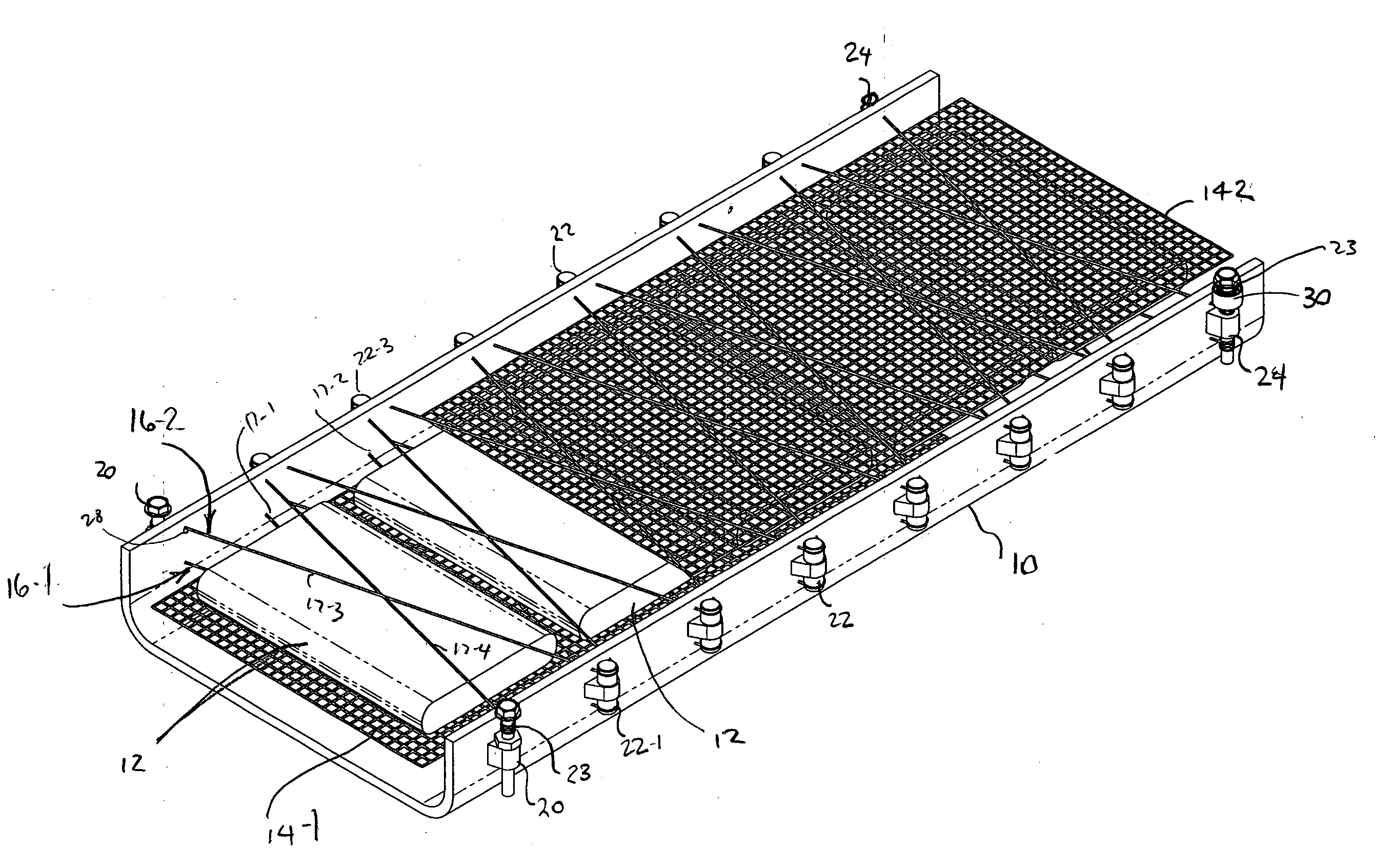
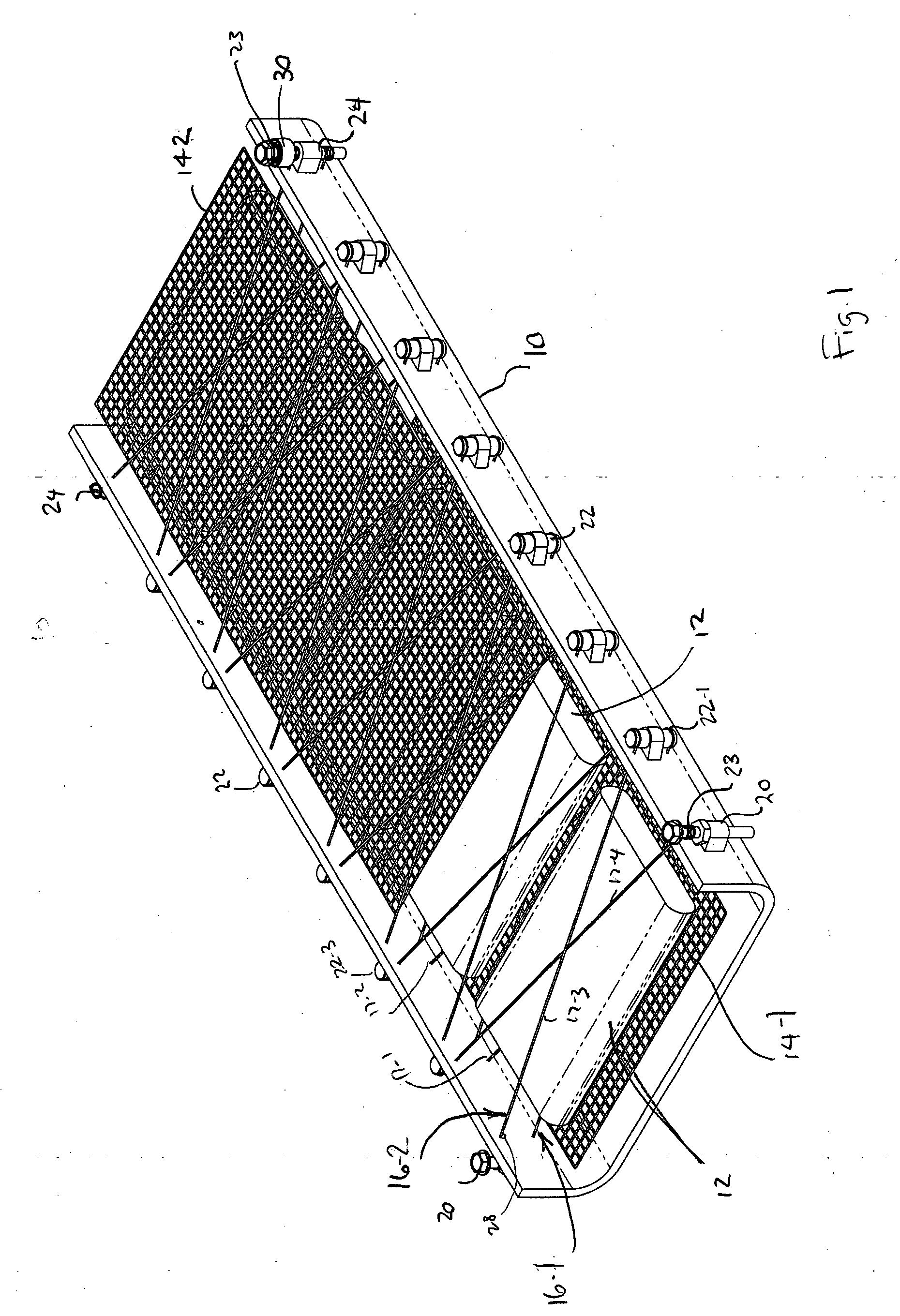
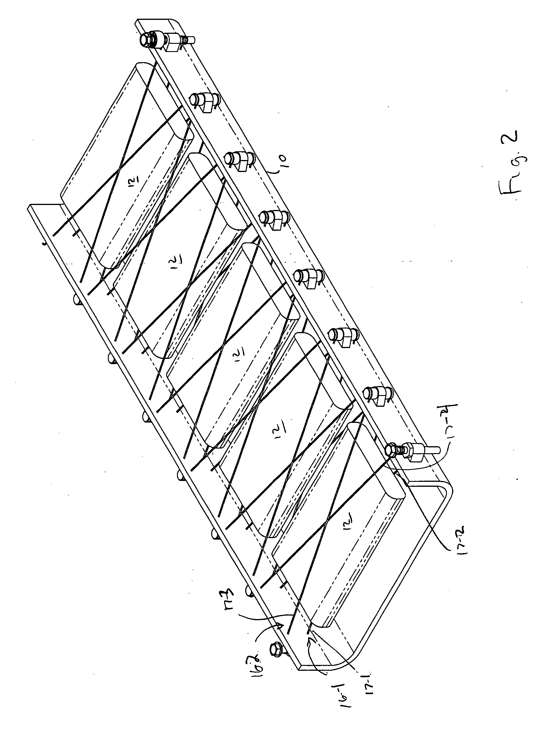
[0007] The present invention is a mechanism for constraining the location of a product (“or other package”) as it moves on a conveyor through a microwave applicator. In one preferred embodiment, the constraint is provided by one or more strings made of a polymer that is transparent to microwave energy. The portion of the constraint mechanism located in the applicator section is ideally limited to including essentially the polymer strings, in order to avoid introducing undesirable interactions with the microwave energy.
[0011] In an alternate embodiment of the basic concept, leaf springs can be used as tensioners. The leaf springs not only hold the strings under tension, but they may have perforations formed therein. If so, the perforations provide improved heat transfer in a fluid-filled applicator.
[0016] The constraining mechanism maintains the location of product packages while they travel through a microwave applicator on a conveyor. This improves uniformity of microwave processing.
[0017] In environments where products also travel through water, vegetable oil, or other fluids while being processed, turbulence is introduced or increased by the constraints, thereby improving mixing and heat transfer.
[0018] Furthermore, movement of the constraints can be detected by a transducer, which provides feedback on the location and condition of the packages. This can be particularly advantageous in detecting malfunctions, such as when a package may have become swollen or blocked during processing.
[0019] Much of the constraint structure can be located outside of the applicator so that it does not interfere with uniform application of microwaves. This also helps ensure that microwave energy does not interfere with the transducers used to determine string deflection.

Problems solved by technology

There is no advantage to having a precisely dimensioned applicator, if consistent positioning of the product within the applicator cannot be assured as it travels down the conveyor.
If a product moves up and down, or from side to side, while being conveyed through applicator, uneven results will occur.
Polypropylene and polyethylene are probably not suitable.

Method used


Image

  • Product guidance system for continuous conveyor microwave oven
  • Product guidance system for continuous conveyor microwave oven
  • Product guidance system for continuous conveyor microwave oven

Examples


Embodiment Construction

[0031] A description of preferred embodiments of the invention follows.

[0032]FIG. 1 illustrates one embodiment of a continuous feed microwave applicator 10 that uses a product constraint mechanism according to the invention. The applicator 10 may be generally rectangular in cross section. In the drawings herein, a top portion or cover of the applicator 10 has been removed, and is not shown, so that the products 12 and internal components can be seen more readily.

[0033] The applicator 10 may be “fluid filled” or “air filled”. It should be understood that the fluids used might be water, vegetable oil, or other fluids. In general, when we refer to “fluid environments” herein, the fluid is typically the same density as the products 12 being processed. Reference to an “air filled” applicator 10 herein includes environments not only where the product is processed in air, but also wherever the product 12 substantially more dense than the surrounding fluid.

[0034] Within the applicator 10...


PUM


Abstract

A constraint mechanism for holding products as they are processed through a microwave applicator, used specifically for constraining products as they travel on one or more continuous conveyors.

Description

RELATED APPLICATION [0001] This application claims the benefit of U.S. Provisional Application No. 60 / 645,376, filed Jan. 20, 2005. The entire teachings of the above application are incorporated herein by reference.BACKGROUND OF THE INVENTION [0002] The present invention relates to conveyors for use in microwave processing, and in particular to a constraint mechanism for holding conveyed items in place. [0003] Volume processing of products with microwave energy, such as needed for large scale cooking, sterilization, and the like, typically uses a transmission system in which the microwave energy and the product being processed travel together through a waveguide applicator. [0004] Many different approaches have been tried to improve the uniformity of results in such systems. These usually involve carefully designing the shape of the waveguide applicator. [0005] In such systems, it also is typically desirable to process as many articles in as short a time as possible. Thus, it is com...

Claims


Application Information

Patent Timeline
IPC IPC(8): H05B6/78
CPCH05B6/782
Inventor WENDEL, THOMAS D.EVES, E. EUGENE IISECOVICH, BRUCE
Owner THE FERRITE
Learn More