Self-aligning and actively compensating refiner stator plate system

a technology of stator plate and refiner, which is applied in the direction of grain treatment, supporting apparatus, manufacturing tools, etc., can solve the problems of not providing for trimming correction, angular orientation, and not revealing any apparatus for carrying out such an adjustmen

Inactive Publication Date: 2006-10-19
THERMO BLACK CLAWSON
View PDF27 Cites 7 Cited by
  • Summary
  • Abstract
  • Description
  • Claims
  • Application Information

AI Technical Summary

Benefits of technology

[0015] In accordance with still another preferred embodiment, the apparatus includes at least three distance sensors mounted on the stator for generating a plurality of sensor signals related to the axial width of the refiner gap at different positions on the refining surface of the stator. In accordance with this embodiment, the preferred controller, or encoder, is programmed to compare the sensor signals with one or more reference values, such as initialized val

Problems solved by technology

One drawback to known refining systems is that they make no provision for correcting errors in the trim, or angular orientation, of the refining elements relative to one another.
Dodson-Edgars teaches that plate tram may be c

Method used


Image

  • Self-aligning and actively compensating refiner stator plate system
  • Self-aligning and actively compensating refiner stator plate system
  • Self-aligning and actively compensating refiner stator plate system

Examples


Embodiment Construction

[0026] Preferred exemplary embodiments of an exemplary dual disc type refining system with actuator controlled positioning of a refining gap will be described herein with reference to FIGS. 1-6. Those of ordinary skill in the art will recognize that the various exemplary embodiments of the invention described herein can be adopted to other conventional forms of refining equipment without undue experimentation.

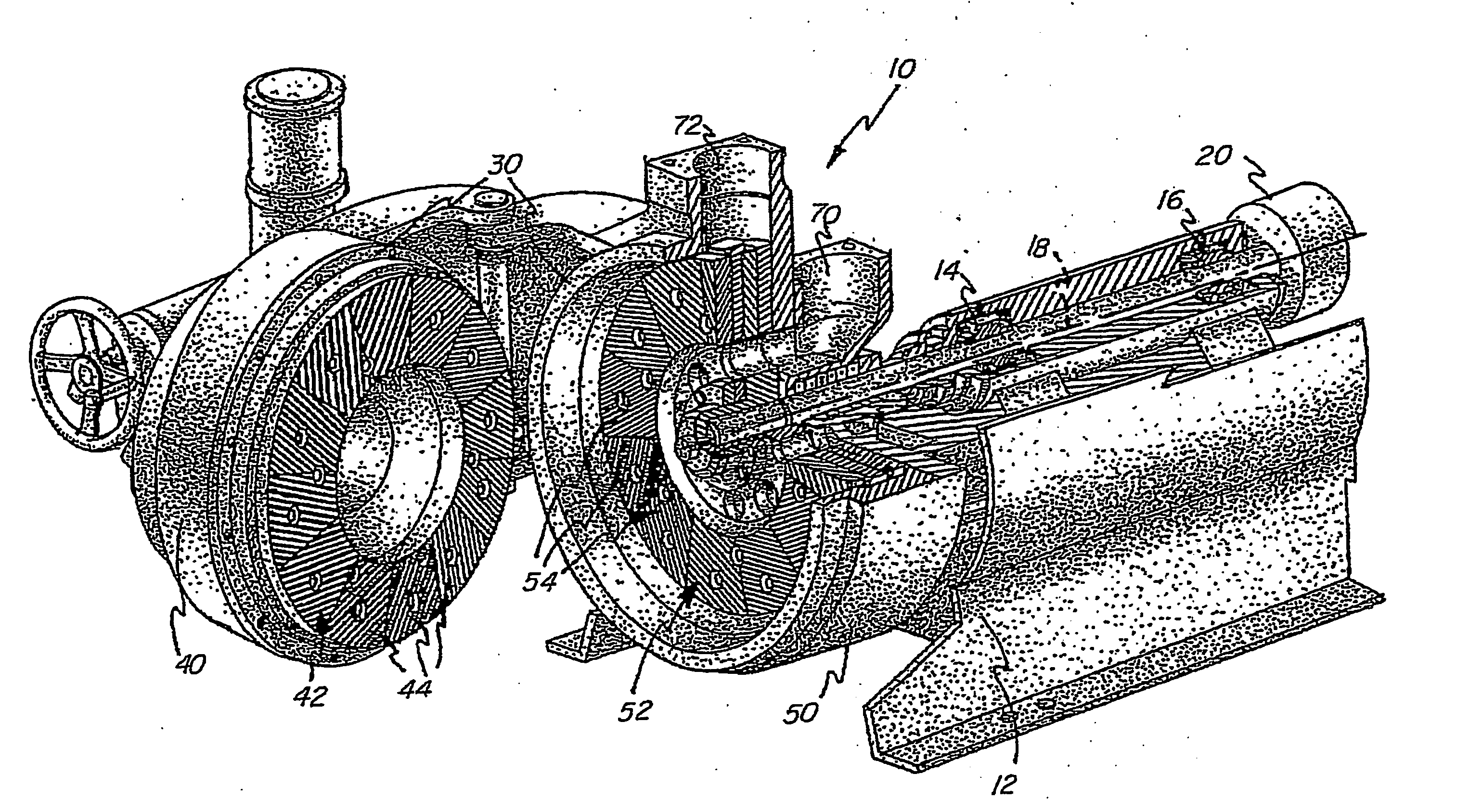
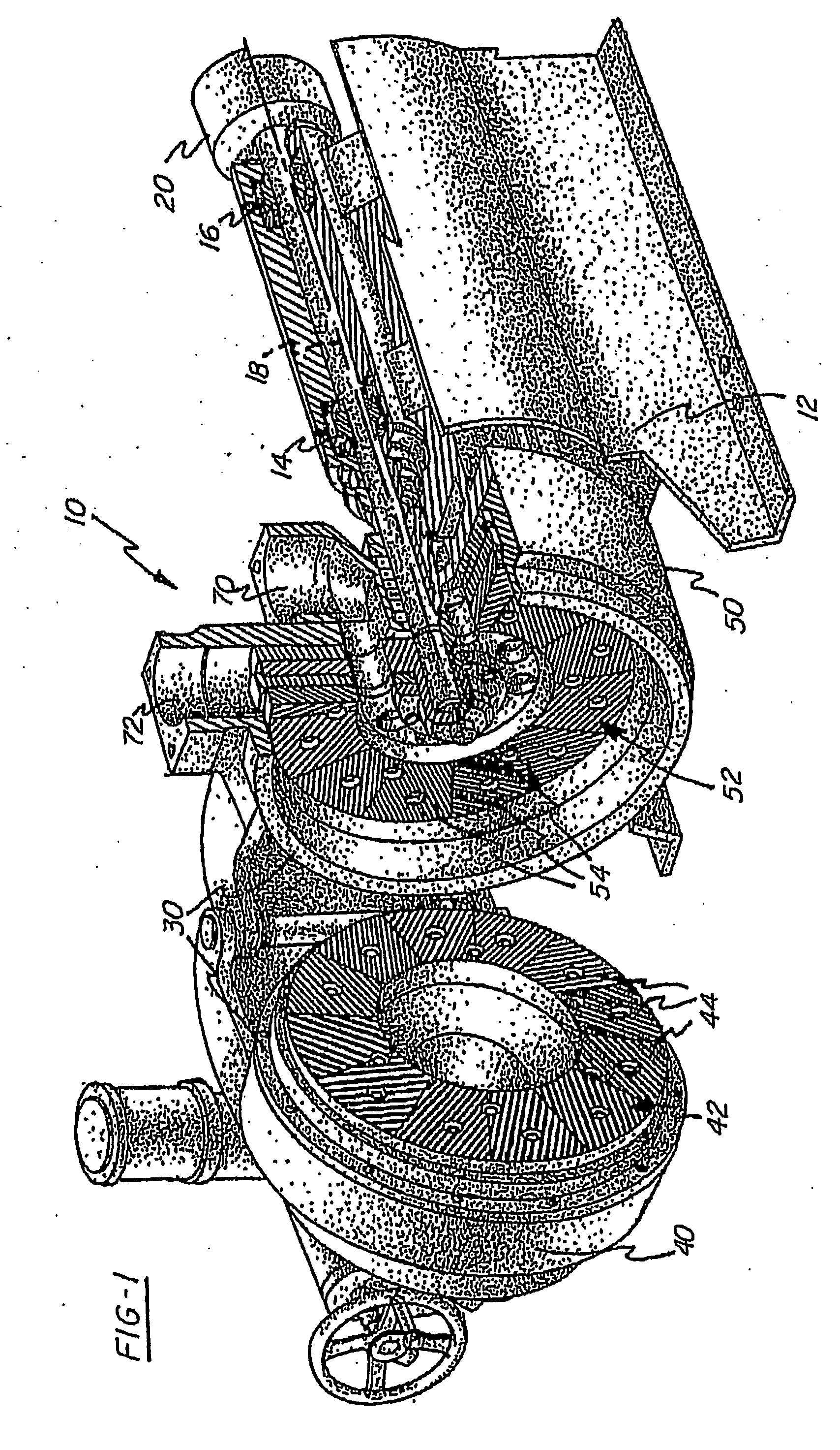
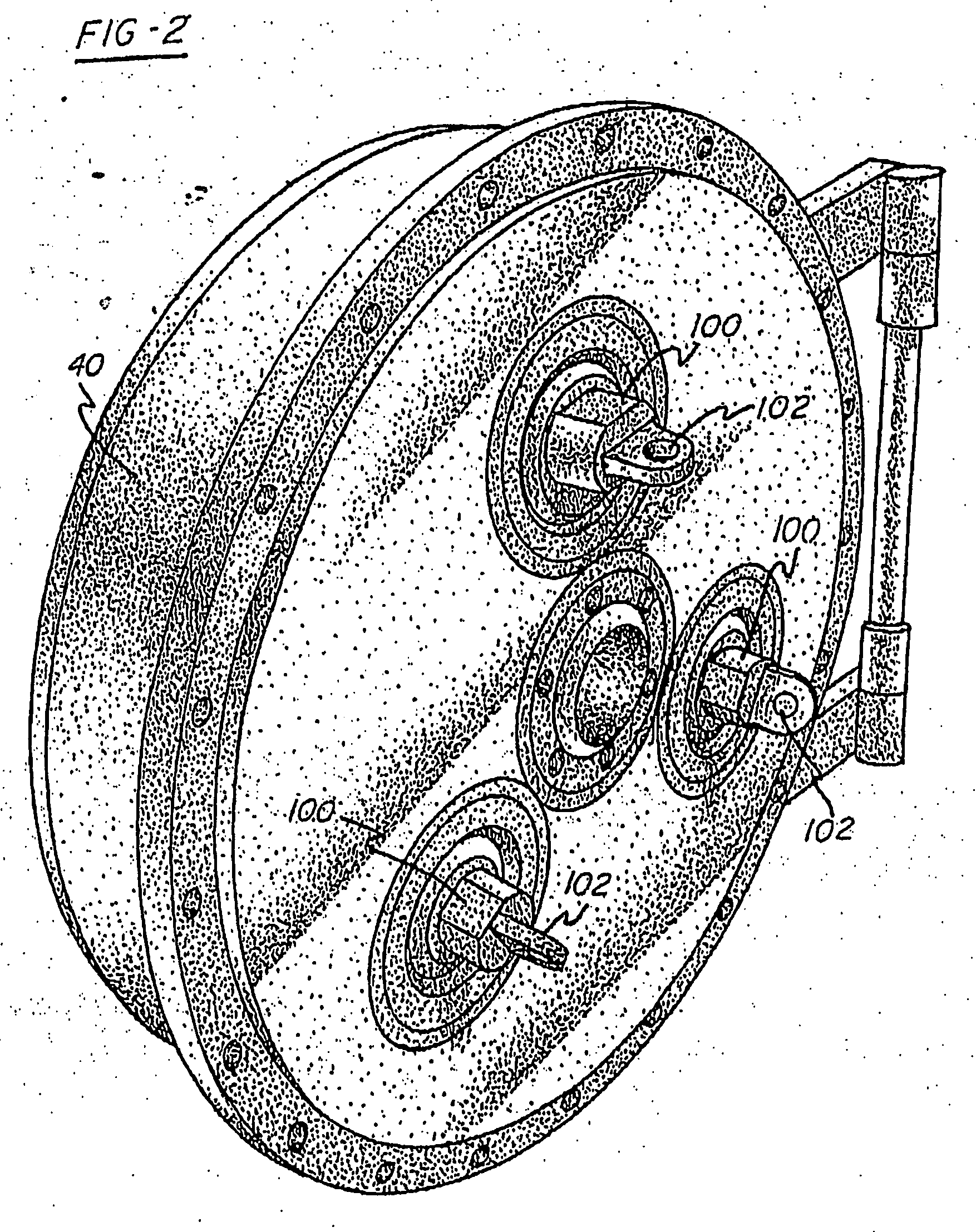
[0027]FIG. 1 shows generally an exemplary embodiment of a dual disc refiner system 10 designed for preferred application in the refining of paper and pulp slurries according to the invention. The refiner 10 incorporates some of the principles and advantages as described in Egan et al. U.S. Pat. No. 5,947,394, issued Sep. 7, 1999; and in Egan et al. International Publication No. WO 99 / 52197, published Oct. 14, 1999, the disclosures of both being incorporated herein by reference. Also, familiarity with paper pulp refiners, including radially positioned disk-type refiner plates w...


PUM

PropertyMeasurementUnit
Temperatureaaaaaaaaaa
Pressureaaaaaaaaaa
Widthaaaaaaaaaa

Abstract

An improvement to a mechanical refining system relates to an apparatus including three or more actuators (100) coupled to a stator (42) of the refining system, and a controller for independently operating the actuators. An improved method of refining permits adjustment of the overall width of a refining gap between refining elements mounted by the stator and a rotor as well as the trim of the refining elements relative to each other

Description

CROSS-REFERENCE TO RELATED APPLICATION [0001] This application claims the priority benefit of U.S. Provisional Patent Application Ser. No. 60 / 477,014 filed Jun. 9, 2003.FIELD OF THE INVENTION [0002] This invention relates to an improved mechanical refiner. More particularly, it relates to an improvement to a mechanical refiner having a stator mounting a first refining element and a rotor mounting a second refining element spaced from said first refining element to define a refining gap. The refining gap and alignment of the trim, or angular orientation, of the refining elements relative to one another are actively maintained according to various conditions of the refining elements or the number of motor revolutions even as the refiner is in use. Actuators are coupled to the stator and a controller to adjust the average or overall width of the refining gap and the trim, or angular orientation, of the stator relative to the rotor, thus providing three or more degrees of control over t...

Claims


Application Information

Patent Timeline
IPC IPC(8): B02C25/00D21D1/00D21D1/30
CPCB02C7/14D21D1/30D21D1/002
Inventor DEMLER, CHRISTOPHERLEGAN III, JOHN J.
Owner THERMO BLACK CLAWSON
Why Eureka
Try Eureka