Display stand for disposable serving containers

a technology for serving containers and display stands, which is applied in the field of display stands, can solve the problems of adversely affecting the stability of the assembled package, the aesthetic appeal of these types of decorative containers is not readily apparent to the customer, etc., and achieves the effects of minimizing the space needed for transportation, facilitating manufacturing, and minimizing the frequency of storag

Inactive Publication Date: 2006-10-19
GEORGIA PACIFIC CORRUGATED
View PDF10 Cites 1 Cited by
  • Summary
  • Abstract
  • Description
  • Claims
  • Application Information

AI Technical Summary

Benefits of technology

[0004] In order for the display stand to be economically viable, it must allow the footprint of the package to remain small and it must allow the various packages of the containers to be nested. This minimizes the space needed to transport the packaged containers and display stands and allows the retail outlet to display a large number of such packaged containers and display stands on the shelves. This in turn minimizes the frequency that the store shelves need to be restocked with those items. In addition, the display stand should be easily manufactured and combined with the consumer product to be displayed with the display stand to allow easy incorporation into the manufacturing process of the consumer products. This will minimize cost for the consumer product manufacturer. The display stand should also work with the retail outlets' current display system to avoid costly retrofitting of the retail outlets' current display system and to avoid the need for the retail outlets to purchase new display systems.
[0005] The display stand of this invention is preferably formed from a paperboard blank that is folded together to define an interior portion for accommodating a certain number of disposable containers. When the containers are placed in the display stand, the display stand holds the containers in a vertical position so the face of the container can be directed to the consumer at the point of purchase. The display stand has an open bottom and is defined by a straight bottom edge where the edges are substantially aligned with each other and generally perpendicular to a vertical axial line extending through the display stand. This straight bottom edge provides a flat surface on which the display stand rests to give the display stand, with the containers therein, stability. The front and rear portions of the display stand preferably have a concavely curved top edge such that the radius of curvature of the concavely curved portions are substantially similar to the radius of curvature of the face portion of the container. This provides the consumer with an unobstructed view of the decorative face of the container. It also provides a shoulder on which the rear of the container can rest so the edges of the containers do not extend below the bottom edge of the display stand, which could adversely affect the stability of the assembled package. The two sides of the display stand can be generally perpendicular to the front and rear portions of the display stand. Alternatively, each of the two sides can be formed from two angled portions so that each end defines a generally V-shaped configuration with the apex of the V pointing away from the containers. These sides of the display stand may also provide a shoulder on which the sides of the container can rest to also help prevent the bottom edge of the containers from extending below the bottom edge of the display stand to thus improve the stability of the package.

Problems solved by technology

When stacked horizontally on store shelves, the aesthetic appeal of these types of decorative containers is not readily apparent to the customer.
It also provides a shoulder on which the rear of the container can rest so the edges of the containers do not extend below the bottom edge of the display stand, which could adversely affect the stability of the assembled package.

Method used


Image

  • Display stand for disposable serving containers
  • Display stand for disposable serving containers
  • Display stand for disposable serving containers

Examples


first embodiment

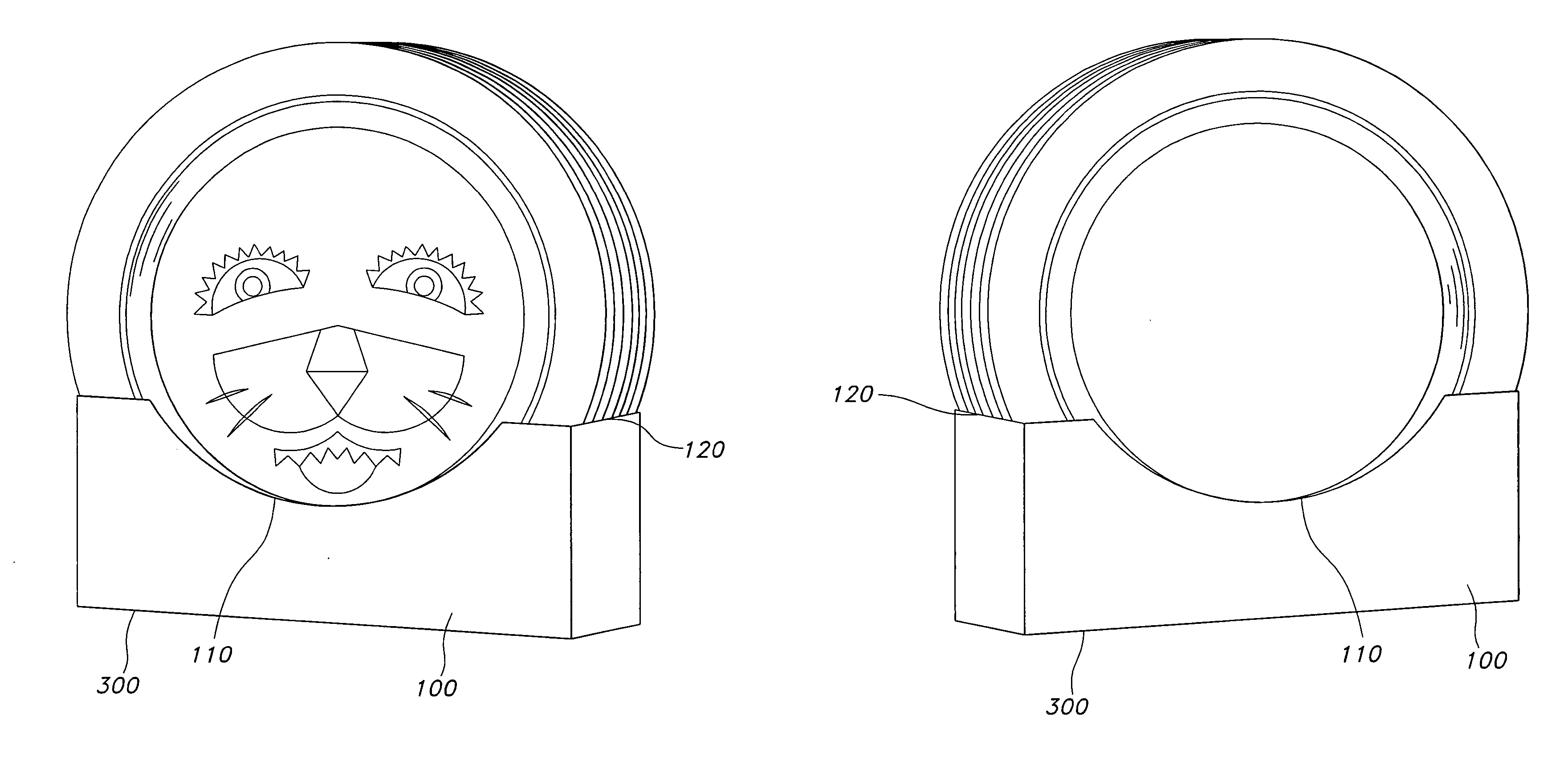
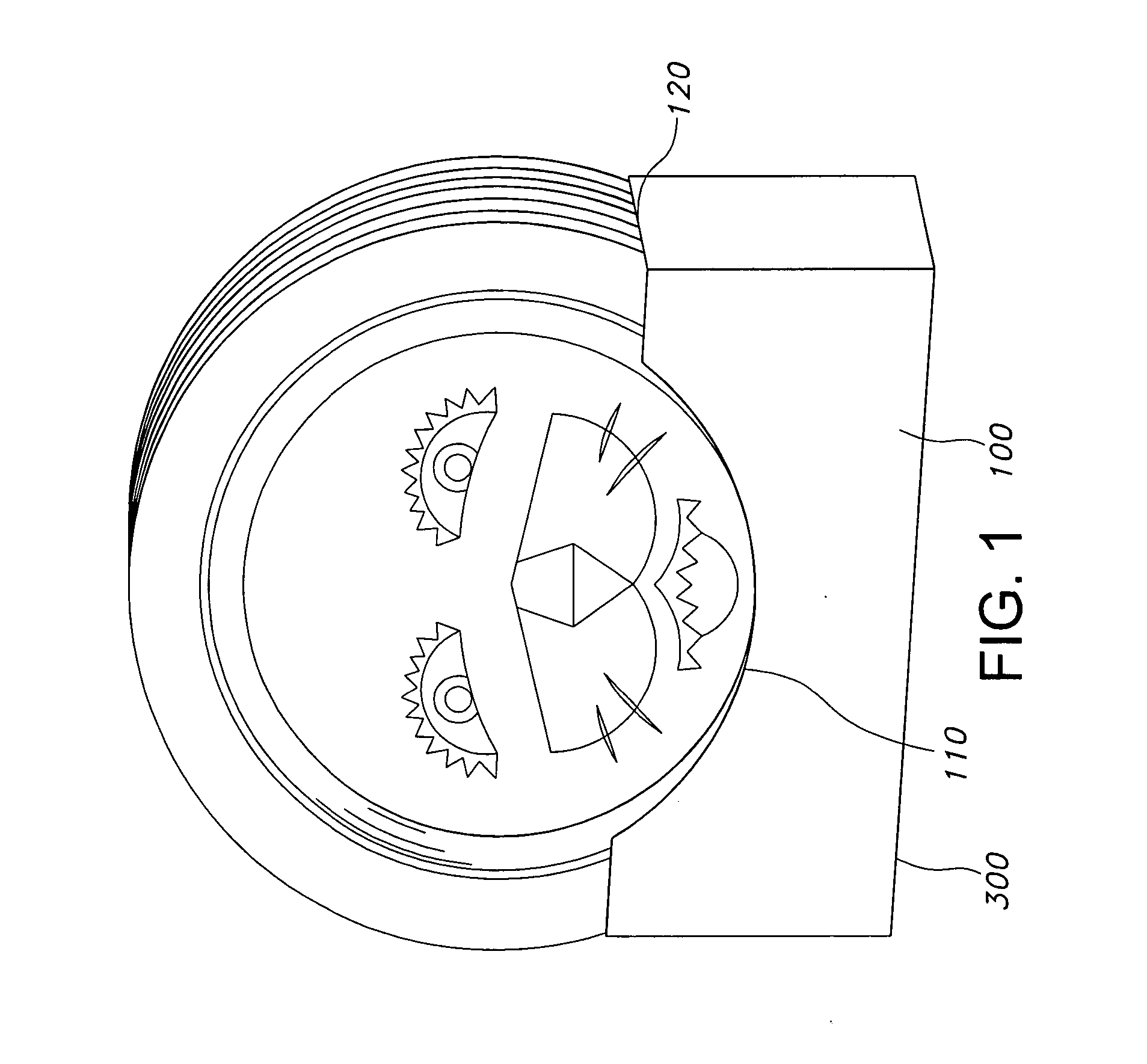
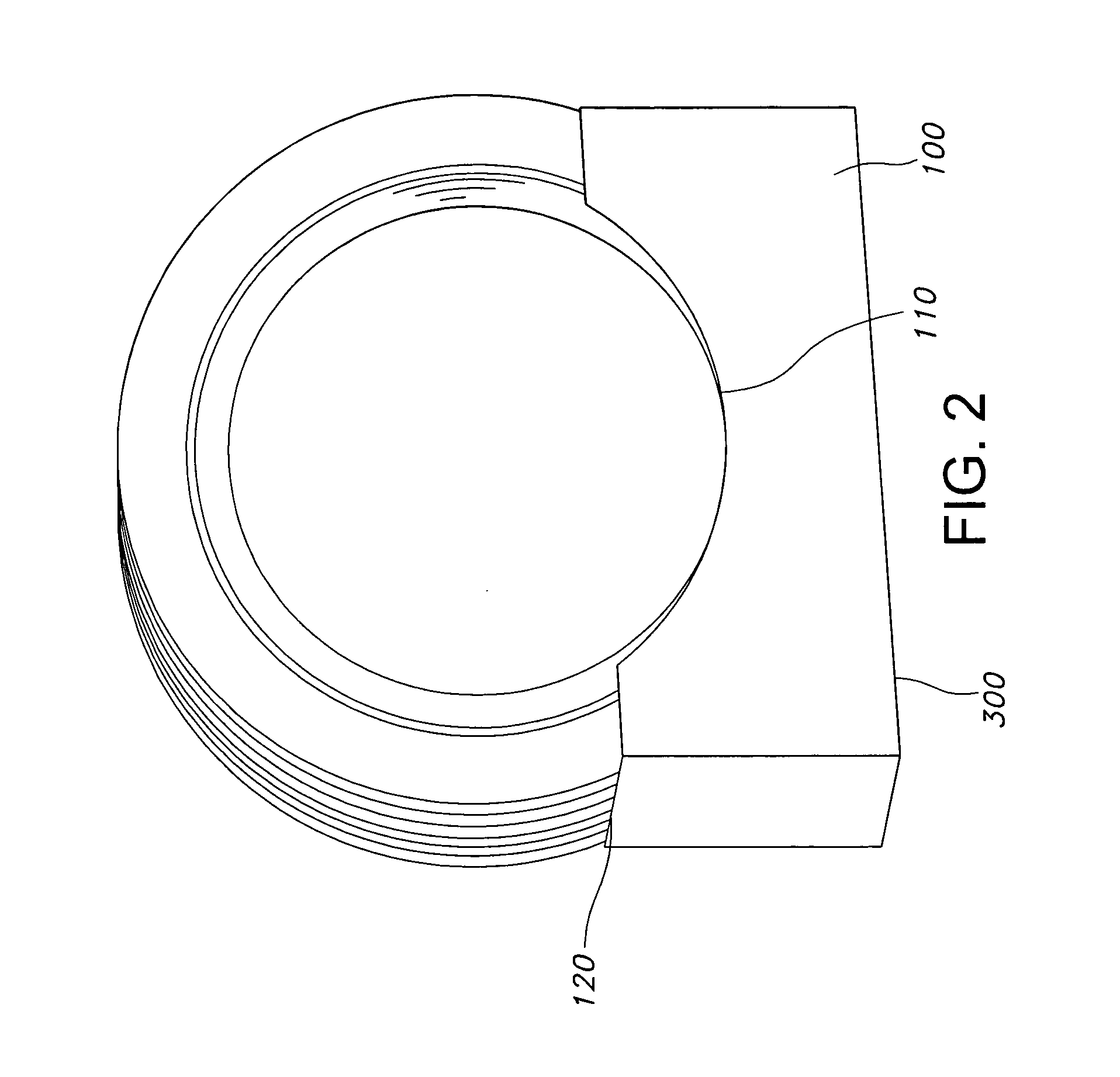
[0020] The blank for display stand 100 has a continuous straight bottom edge 300, a connection tab 410, a front flap 420, a first end flap 430, a rear flap 440 and a second end flap 450. As seen in FIG. 4, connection tab 410 is connected along its right edge to the left edge of front flap 420 along a first vertical fold line 415. Front flap 420 is connected along its right edge to the left edge of first end flap 430 along a second vertical fold line 425. First end flap 430 is connected along its right edge to the left edge of rear flap 440 along a third vertical fold line 435. Rear flap 440 is connected along its right edge to the left edge of second end flap 450 along a fourth vertical fold line 445. To assemble the blank into display stand 100, each vertical fold line is folded so that each portion of the blank is perpendicular to the adjacent portion. This allows connection tab 410 to overlap a portion of second end flap 450 and can be adhered thereto by any standard means such a...

second embodiment

[0021] The blank for display stand 100′ has a continuous straight bottom edge 300, first rear flap 510, a first end flap 520, a second end flap 530, a front flap 540, a third end flap 550, a fourth end flap 560 and a second rear flap 570. As seen in FIG. 8, first rear flap 510 is connected along its right edge to the left edge of first end flap 520 along a first vertical fold line 515. First end flap 520 is connected along its right edge to the left edge of second end flap 530 along a second vertical fold line 525. Second end flap 530 is connected along its right edge to the left edge of front flap 540 along a third vertical fold line 535. Front flap 540 is connected along its right edge to the left edge of third end flap 550 along a fourth vertical fold line 545. Third end flap 550 is connected along its right edge to the left edge of fourth end flap 560 along a fifth vertical fold line 555. Fourth end flap 560 is connected along its right edge to the left edge of second rear flap ...


PUM


Abstract

A display stand for disposable serving ware containers, such as paper or plastic plates, platters, deep dishes or bowls that displays the containers in a vertical position so the face of the container can be readily viewed by the consumer at the point of purchase.

Description

[0001] This application claims the benefit of priority of U.S. Provisional Patent Application No. 60 / 672,733, filed Apr. 19, 2005, which is hereby incorporated by reference in its entirety.BACKGROUND OF THE INVENTION [0002] This invention relates to a display stand for certain types of consumer products. More particularly, this invention relates to a display stand for disposable serving ware containers, such as paper or plastic plates, platters, deep dishes or bowls that will display the containers in a vertical position so the face of the container can be readily viewed by the consumer at the point of purchase. BRIEF SUMMARY OF THE INVENTION [0003] Serving containers, such as paper or plastic plates are typically packaged in nested form in a plastic outer wrap. The containers are transported from the manufacturer ultimately to a retail outlet for purchase by the consumer. At the retail outlet, the containers are typically stacked horizontally on the shelves such that the consumer o...

Claims


Application Information

Patent Timeline
Patent Type & Authority Applications(United States)
IPC IPC(8): A47B97/04
CPCB65D5/52A47F7/0064
Inventor SMITH, TRACY C.
Owner GEORGIA PACIFIC CORRUGATED
Why Eureka
Try Eureka