Compensation circuit for compensating non-uniformity according to change of operating temperature of bolometer

a technology of compensation circuit and bolometer, which is applied in the field of bolometer, can solve the problems of non-uniformity of reactivity on the operating temperature existing on the bolometer material itself, inability to substantially amend the non-uniformity of reactivity, and constant maintenance of the operating temperature of the ir detector, etc., and achieves the effect of simple circuit for non-uniformity amendmen

Inactive Publication Date: 2006-10-19
KOREA ADVANCED INST OF SCI & TECH
View PDF4 Cites 50 Cited by
  • Summary
  • Abstract
  • Description
  • Claims
  • Application Information

AI Technical Summary

Benefits of technology

[0032] Accordingly, the present invention can compensate non-uniformity due to the operating temperature changes existing in a IR detector over a broad range of operating temperatures.
[0033] It is also possible to eliminate the need for a temperature maintaining device used in a bolometer by using a compensation circuit.
[0034] By eliminating the temperature maintaining device, it is also possible to provide a small sized IR detector using bolometer and to provide a simple circuit for non-uniformity amendment.

Problems solved by technology

Although the bolometer is configured using a semiconductor process, it is not an accurate IR detector because the characteristics per pixel configuring each bolometer are different from each other owing to factors such as material characteristics or change of process.
The 2 point method amendment, however, has a critical problem in that the non-uniformity of reactivity on the operating temperature existing on the bolometer material itself cannot be substantially amended.
An additional problem is that when the 2 point method amendment is performed, the operating temperature of the IR detector must be constantly maintained as the 2 point method is only efficient when the the IR detector operating temperature is constantly maintained.
However, using a Thermo-Electric cooler increases power consumption, volume, and costs.
If Thermo-Electric cooler is not used, to maintain the operating temperature of the IR detector, the 2 point method amendment will not be able to eliminate above described non-uniformity problem.
Although the range of amendable temperatures is broader than that of conventional 2 point method, non -uniformity of reactivity on operating temperature existing bolometer material itself cannot be substantially amended.
Hence, the need for maintaining temperature of system using bolometer cannot be substantially eliminated.

Method used


Image

  • Compensation circuit for compensating non-uniformity according to change of operating temperature of bolometer
  • Compensation circuit for compensating non-uniformity according to change of operating temperature of bolometer
  • Compensation circuit for compensating non-uniformity according to change of operating temperature of bolometer

Examples


Embodiment Construction

[0043] Preferred embodiments of the present invention will be described in a more detailed manner with reference to the drawings.

[0044] A compensation circuit according to the present invention comprises a biasing part including a first transistor generating bias current according to the change of operating temperature to have a dependency of exponential function for the operating temperature of circuit, and a second transistor turned on / off according to the column signal of a bolometer array; a bolometer part including a variable resistor for detecting IR in a pixel base, a third transistor turned on / off according to the column signal of a bolometer array coupled to one end of the variable resistor, and a fourth transistor turned on / off according to the row signal of a bolometer array coupled to the other end of the variable resistor; and an off-set compensation part for compensating the non-uniformity of the bolometer part.

[0045] In accordance with the present invention, the fir...


PUM


Abstract

The present invention relates to a bolometer, and more specifically to a compensation circuit for compensating non-uniformity due to the difference of operating temperature between bolometers which exist in bolometer array using semiconductor material. A compensation circuit according to the present invention comprises a biasing part including a first transistor generating bias current according to the change of operating temperature to have a dependency of exponential function for the operating temperature of circuit, and a second transistor turned on/off according to the column signal of a bolometer array; a bolometer part including a variable resistor for detecting IR in a pixel base, a third transistor turned on/off according to the column signal of a bolometer array coupled to one end of the variable resistor, and a fourth transistor turned on/off according to the row signal of a bolometer array coupled to the other end of the variable resistor; and an off-set compensation part for compensating the non-uniformity of the bolometer unit.

Description

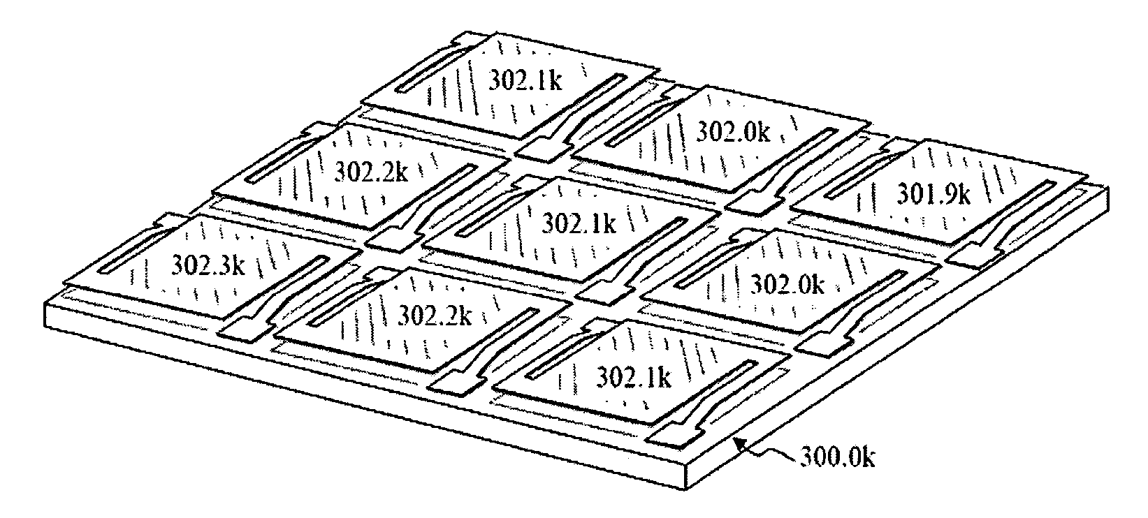
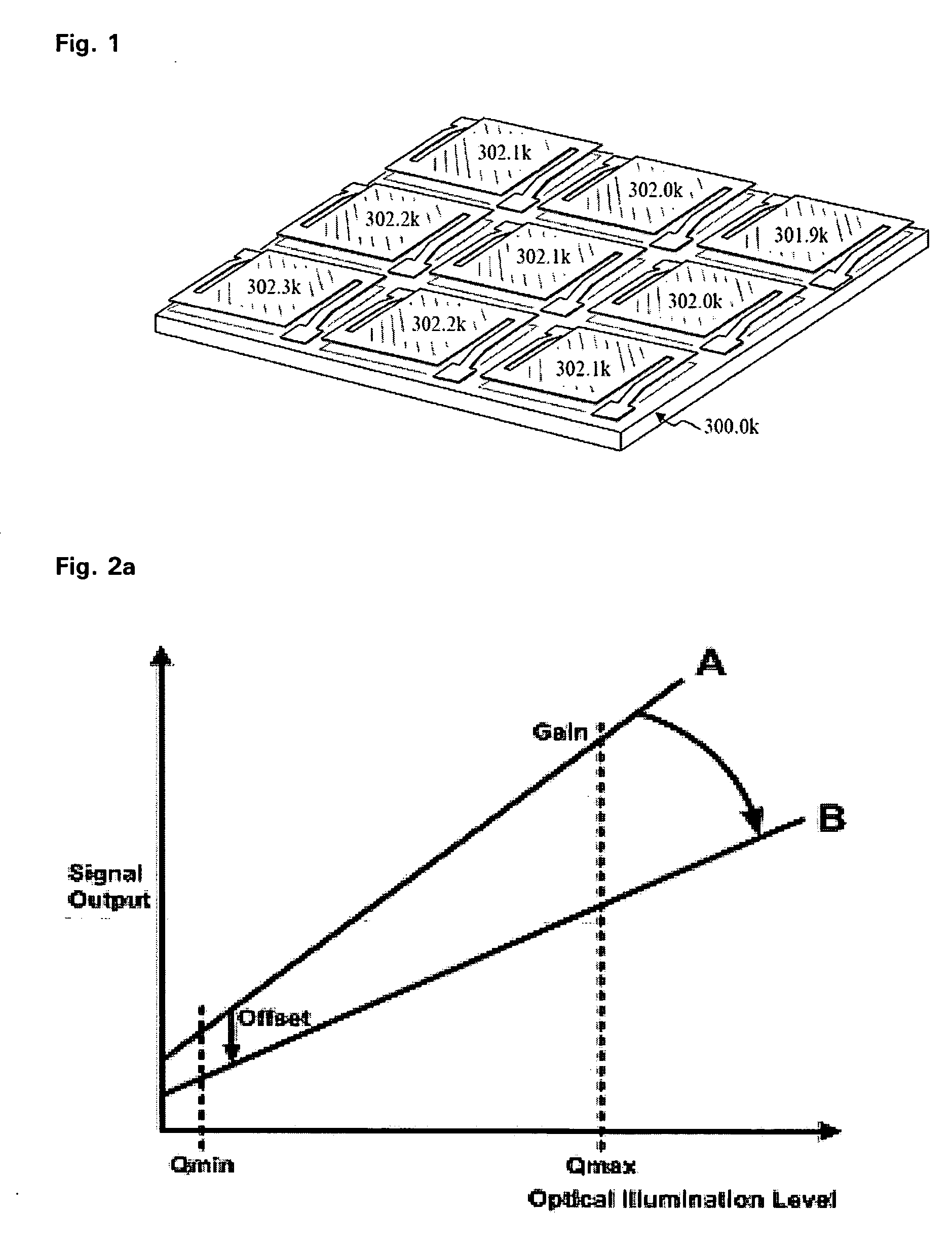
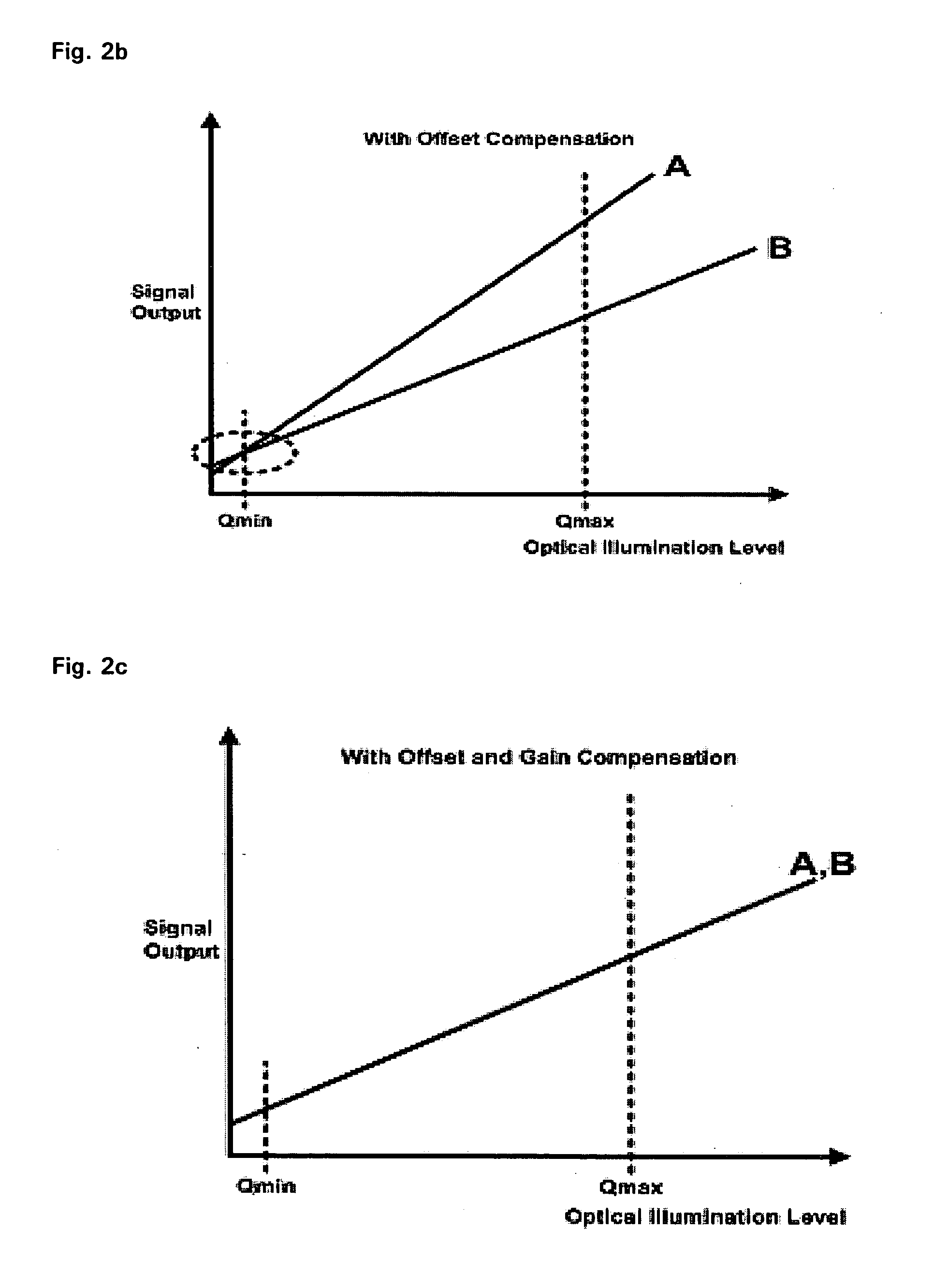
[0001] This Nonprovisional application claims priority under 35 U.S.C. §119(a) on Patent Application No. 10-2005-0031339 filed in Republic of Korea on Apr. 15, 2005, the entire contents of which are hereby incorporated by reference. BACKGROUND OF THE INVENTION [0002] 1. Field of the Invention [0003] The present invention relates to a bolometer, and more specifically to a compensation circuit for compensating non-uniformity due to the difference of operating temperatures between bolometers existing in a bolometer array using semiconductor material. [0004] 2. Description of the Background Art [0005]FIG. 1 generally represents an IR(lnfra Red)detector configured by a bolometer with an array of 3×3(3 rows 3 columns) using a semiconductor process. [0006] As shown in FIG. 1, the IR(lnfra Red)detector configured by the bolometer with the array of 3×3(3 rows 3 columns)is formed using the semiconductor process. However, it detects respectively different values, which are the temperatures of ...

Claims


Application Information

Patent Timeline
Patent Type & Authority Applications(United States)
IPC IPC(8): G01J5/00
CPCG01J5/24H04N5/3651H04N5/33H04N25/673H04N25/671G06Q50/10G06Q50/265G01T1/167G06Q10/0833
Inventor LEE, HEE CHULHWANG, CHI HOLEE, YONG SOOKANG, SANG GU
Owner KOREA ADVANCED INST OF SCI & TECH
Why Eureka
Try Eureka