Display device and method for driving a display device

a display device and display device technology, applied in the field of image display devices, can solve problems such as cost increase, and achieve the effect of high resolution

Inactive Publication Date: 2006-10-19
PANASONIC LIQUID CRYSTAL DISPLAY CO LTD +1
View PDF13 Cites 44 Cited by
  • Summary
  • Abstract
  • Description
  • Claims
  • Application Information

AI Technical Summary

Benefits of technology

[0008] The present invention provides a display device that displays an image and a method for driving the display device by a little modifying a conventional display device, which offers a high resolution, without the necessity of a memory whose storage capacity is large enough to hold pixels constituting a screen image displayed on the display device.
[0015] According to the present invention, a high-resolution display device having an existing data driver circuit partly modified and including demultiplexer circuits can support multiscanning, offer a high resolution, and display existing contents. The present invention can be constructed by merely partly modifying an existing data driver circuit. Consequently, the multiscanning feature can be implemented in the display device with the same cost as the one currently required for peripheral circuits and the same man-hours required for designing as currently required ones.
[0016] Moreover, the present invention can be effectively adapted, especially, to a display device to be included in a portable cellular phone or a personal digital assistant.

Problems solved by technology

This triggers a concern about a rise in a cost.

Method used


Image

  • Display device and method for driving a display device
  • Display device and method for driving a display device
  • Display device and method for driving a display device

Examples


first embodiment

[0028] Referring to FIG. 1 to FIG. 5, a description will be made of an active matrix type display device and a driving method in accordance with the present invention. A liquid crystal display device will be taken as an example of the active matrix type display device. The present invention can also be adapted to an active matrix type display device employing organic electroluminescence (EL) or the like.

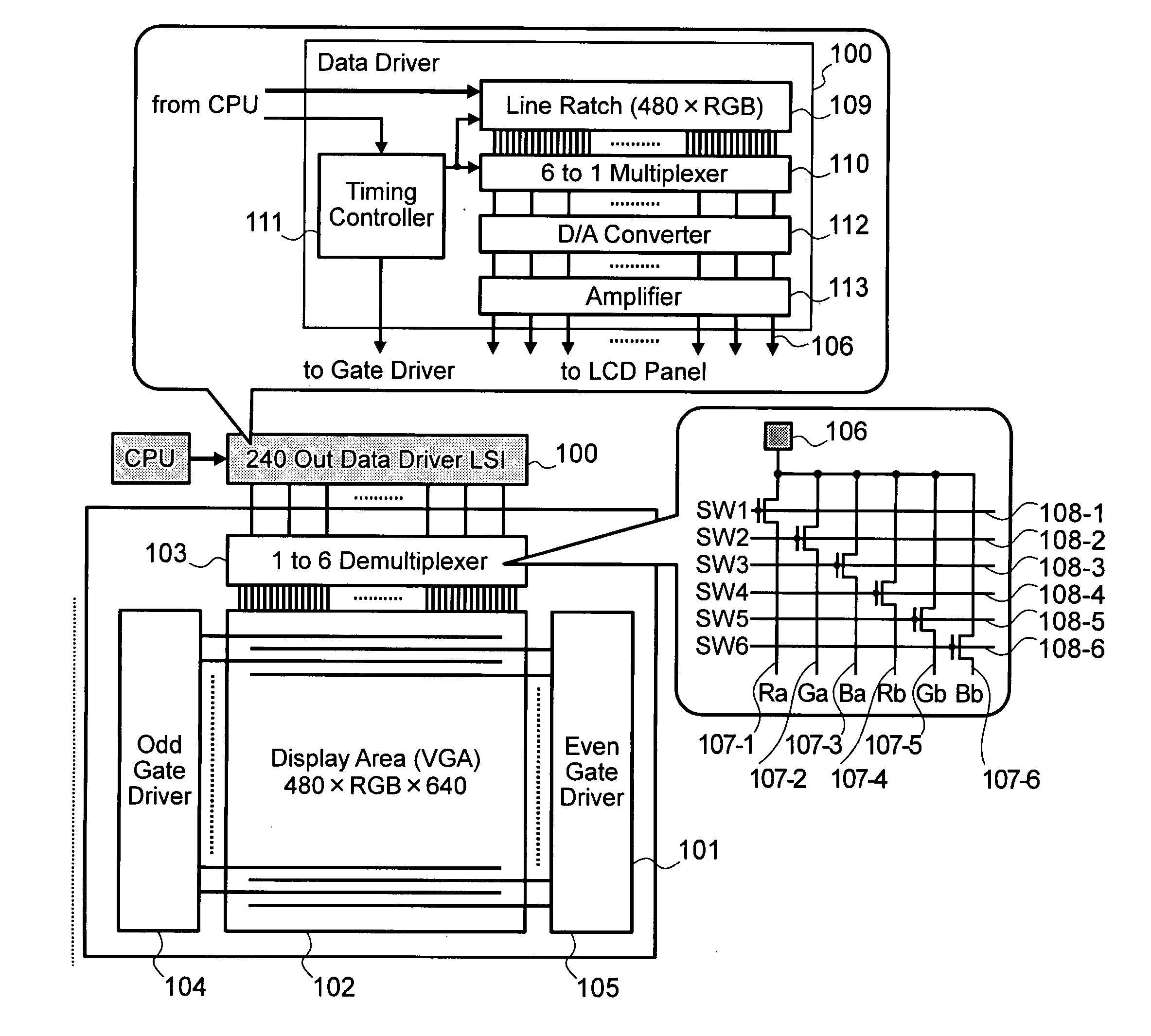
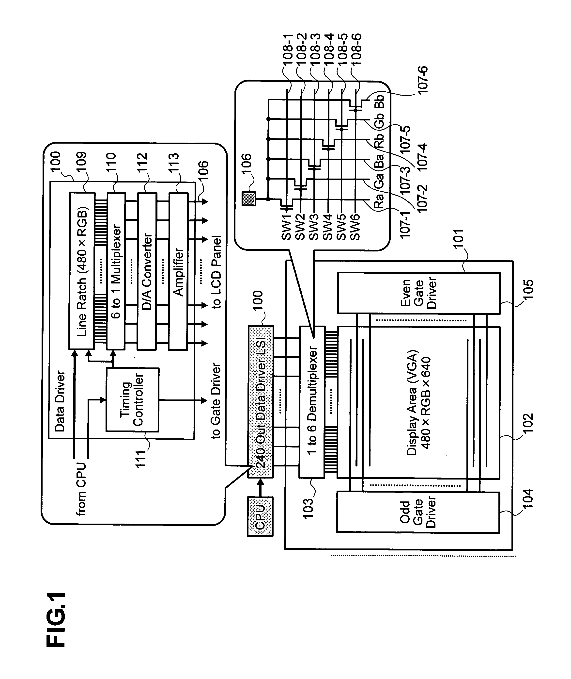
[0029]FIG. 1 shows the configuration of a liquid crystal display device in accordance with the present embodiment. The liquid crystal display device includes a data driver circuit 100 and a liquid crystal panel 101. The liquid crystal panel 101 includes a VGA-conformable display area 102, demultiplexer circuits 103 each including one input port and six output ports, an odd-line gate driver circuit 104 including three hundred and twenty output ports, and an even-line gate driver circuit 105 including three hundred and twenty output ports.

[0030] Each of the demultiplexer circuits 103...

second embodiment

[0060] An active matrix type display device and a driving method in accordance with the present invention will be described in conjunction with FIG. 6 to FIGS. 8A to 8C.

[0061]FIG. 6 shows the configuration of a liquid crystal display device in accordance with the present invention. The liquid crystal display device includes a data driver circuit 600 and a liquid crystal panel 601. The data driver circuit 600 is identical to a conventional data driver LSI having two hundred and forty output ports and supporting the QVGA graphic standard except that a line latch circuit and a timing signal generator included therein are slightly modified. The liquid crystal panel 601 includes a display area 602 which offers a resolution of 320 horizontal pixels by three colors of red, green, and blue by 426 vertical pixels (hereinafter, a QVGA×4 / 3 resolution) and in which the long side of QVGA data can be displayed horizontally, one-input four-output demultiplexer circuits 603, an odd-line gate drive...

third embodiment

[0084] An active matrix type display device and a driving method in accordance with the present invention will be described in conjunction with FIG. 9 to FIGS. 11A and 11B.

[0085]FIG. 9 shows the configuration of a liquid crystal display device in accordance with the present invention. The liquid crystal display device includes a data driver circuit 900 and a liquid crystal panel 901. The data driver circuit 900 includes a frame memory 406 and a line latch circuit 401 that latches data representing one line in a display area. The frame memory 406 and line latch circuit 401 are shown in FIG. 4. The line latch circuit 401 holds an input of display data transferred from a system to the data driver circuit 400 (hereinafter an external input) and an input of display data received from the frame memory 406.

[0086] The liquid crystal panel 901 includes a display area 902 offering a resolution of 480 horizontal pixels by three colors of red, green, and blue by 320 vertical pixels (which sha...


PUM


Abstract

A demultiplexer circuit selects one of data signals, which are sent via an output port of a data driver circuit, on a time division basis, and distributes the data signals to data lines. For high-resolution display, the demultiplexer sequentially distributes data signals to associated data lines. For low-resolution display, the demultiplexer distributes identical data signals to data lines or parts of the data lines. Gate driver circuits each sequentially drive scan lines for high-resolution display, and concurrently or temporarily concurrently drive the scan lines for low-resolution display.

Description

CLAIM OF PRIORITY [0001] The present application claims priority from Japanese application serial no. 2005-120848 filed on Apr. 19, 2005, the content of which is hereby incorporated by reference into this application. BACKGROUND OF THE INVENTION [0002] 1. Field of the Invention [0003] The present invention relates to an image display device such as a liquid crystal display, or more particularly, to an active matrix type display device that supports multiscanning and a method for driving the display device. [0004] 2. Description of the Related Art [0005] Active matrix type display devices including a thin-film transistor (TFT) liquid crystal display device have been adopted as a display device to be included in a portable cellular phone or a personal digital assistant owing to such features as a thin lightweight style and low power consumption. In particular, as far as the portable cellular phone is concerned, the improvement in a resolution to be offered by the display device is pro...

Claims


Application Information

Patent Timeline
Patent Type & Authority Applications(United States)
IPC IPC(8): G09G3/36
CPCG09G3/3688G09G2340/0407G09G2310/0297G09G2310/027
Inventor KUDO, YASUYUKISHOJI, TAKASHIMAMBA, NORIOMATSUDO, TOSHIMITSU
Owner PANASONIC LIQUID CRYSTAL DISPLAY CO LTD
Why Eureka
Try Eureka