Display device, driving method of the display device, and electronic device

Active Publication Date: 2006-10-19
SEMICON ENERGY LAB CO LTD
View PDF67 Cites 55 Cited by
  • Summary
  • Abstract
  • Description
  • Claims
  • Application Information

AI Technical Summary

Benefits of technology

[0037] According to the invention, a pseudo contour can be reduced. Therefore, image quality is improved so that a clear image can be displayed. In addition, the duty ratio is improved as compared to the conv

Problems solved by technology

It is known that a display defect called a pseudo contour (or a false contour) occurs when such a time gray scale method is used.
Therefore, in order to realize the same average luminance as in the case of no

Method used


Image

  • Display device, driving method of the display device, and electronic device
  • Display device, driving method of the display device, and electronic device
  • Display device, driving method of the display device, and electronic device

Examples


embodiment mode 1

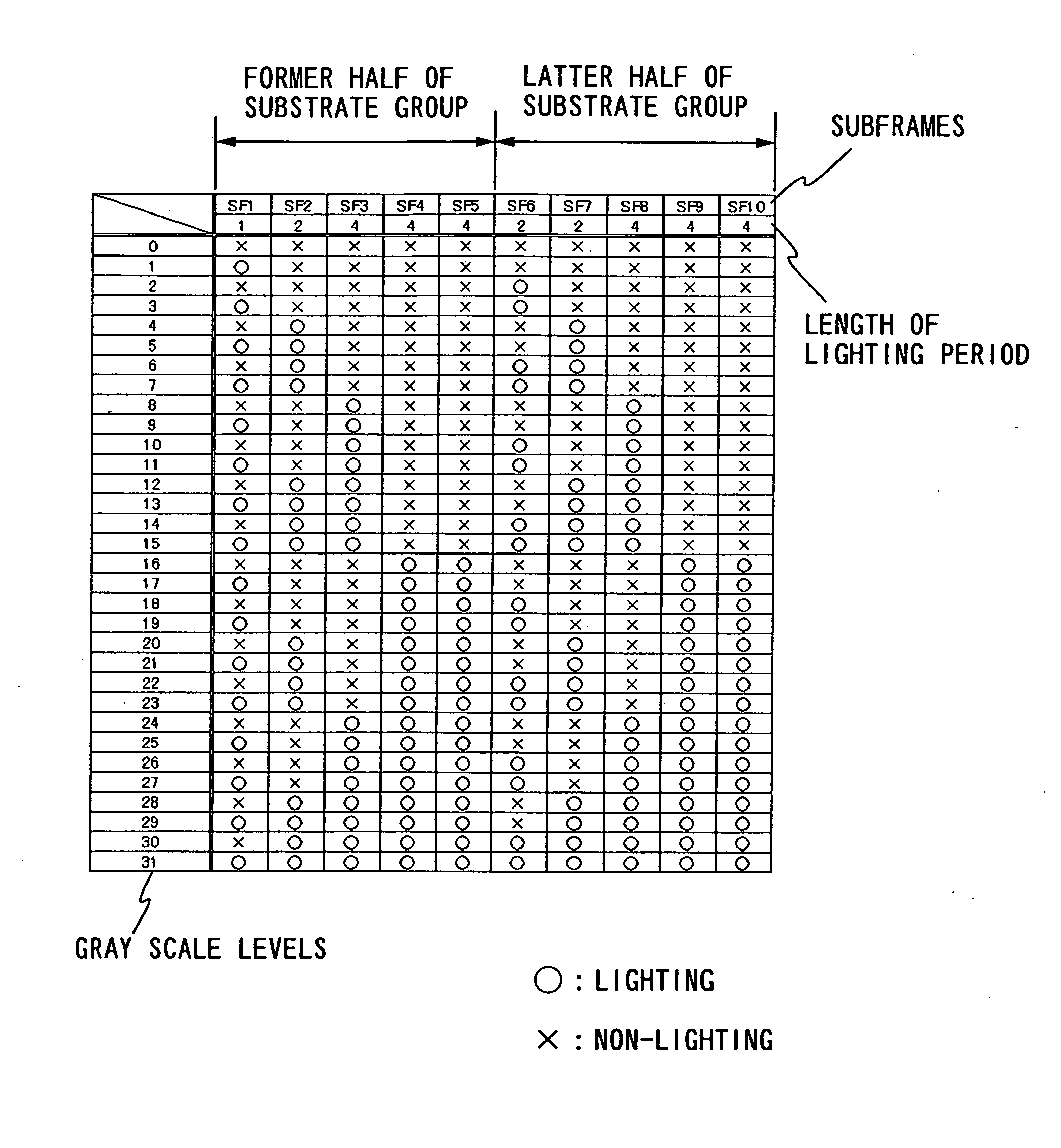
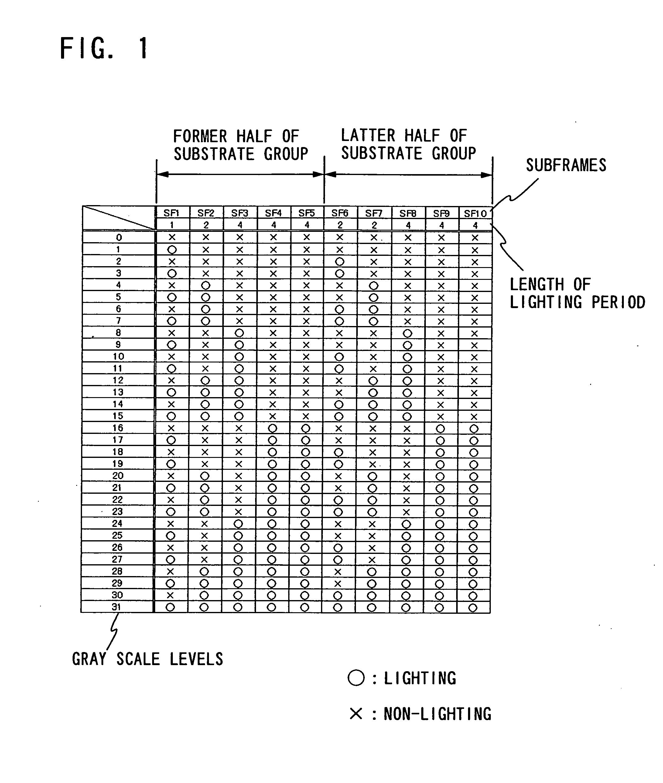
[0101] Described in this embodiment mode is an example in which a driving method of the invention is applied to the case of a 5-bit display (32 gray-scale levels) and is applied to the case of a 6-bit display (64 gray-scale levels).

[0102] In an example of a driving method of this embodiment mode, according to a conventional time gray scale method, a subframe corresponding to a bit belonging to a first bit group is divided into four, a subframe corresponding to a bit belonging to a second bit group is divided into two, and a subframe corresponding to a bit belonging to a third bit group is not divided. Then, one frame is divided into two subframe groups which are a former half and a latter half, and each two of the divided bits belonging to the first bit group are arranged in each subframe group. One of the divided bits belonging to the second bit group is arranged in each subframe group, and the bits belonging to the third bit group are arranged in one or both of the subframe group...

embodiment mode 2

[0186] Described in Embodiment Mode 1 is the case where one frame is divided into two subframe groups. However, according to the driving method of the invention, one frame can also be divided into three or more subframe groups. In this embodiment mode, therefore, description is made on the case where one frame is divided into three or more subframe groups, as an example. Note that the number of subframe groups is not limited to 2 or 3, and may be arbitrarily determined.

[0187] According to an example of a driving method of this embodiment mode, according to a conventional time gray scale method, subframes corresponding to bits belonging to a first bit group are divided into 6, subframes corresponding to bits belonging to a second bit group are divided into 3, and subframes corresponding to bits belonging to a third bit group are not divided, first. Then, one frame is divided into three subframe groups, and each two of the divided bits belonging to the first bit group are arranged in...

embodiment mode 3

[0204] In this embodiment mode, description is made on an example of a timing chart. Although the selection method of subframes in FIG. 1 is used as an example of a selection method subframes, the invention is not limited to this. The invention can easily be applied to another selection method of subframes, another number of gray scale levels, and the like.

[0205] In addition, although an appearance order of subframes is an order of SF1, SF2, SF3, SF4, SF5, SF6, SF7, SF8, FS9, and SF10 as an example, the invention is not limited to this and can be applied to another order as well.

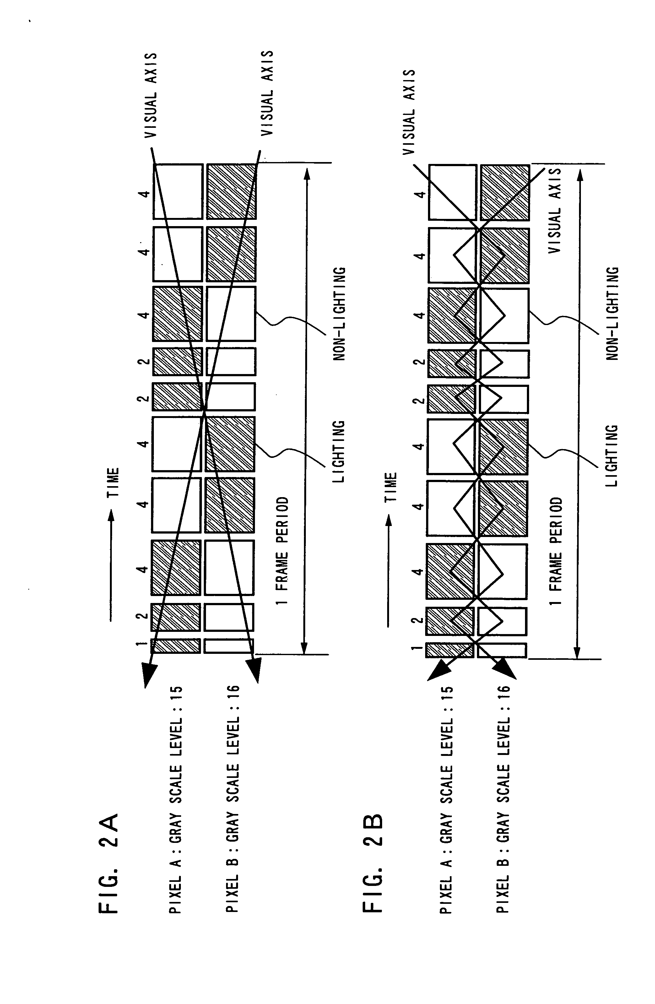
[0206] First, FIG. 24 shows a timing chart in the case where a period of writing a signal to a pixel and a period of lighting are separated. At first, signals for one screen are input to all pixels in a signal writing period. During this period, the pixels do not emit light. After the signal writing period, a lighting period begins and a pixel emits light. The length of the lighting period at this time is ...


PUM


Abstract

To reduce a pseudo contour which occurs when displaying by a time gray scale method. When gradation is expressed with an n bit, the bits are divided into three bit groups, and one frame is divided into two subframe groups. Then, a (0<a<n) subframes corresponding to bits belonging to a first bit group are divided into three or more, each about half of which is arranged in each subframe group; b (0<b<n) subframes corresponding to bits belonging to a second bit group are divided into two, each one of which is arranged in each the subframe group; and c (0≦c<n and a+b+c=n) subframes corresponding to bits belonging to a third bit group are arranged in at least one of the subframe groups.

Description

BACKGROUND OF THE INVENTION [0001] 1. Field of the Invention [0002] The present invention relates to a display device and a driving method thereof, particularly to a display device to which a time gray scale method is applied. [0003] 2. Description of the Related Art [0004] In recent years, a so-called self-luminous display device in which a pixel is formed using a light emitting element such as a light-emitting diode (LED) has attracted attention. As a light emitting element used for such a self-luminous display device, an organic light emitting diode (OLED) (also referred to as an “organic EL element”, an “electroluminescence (EL) element”, or the like) has attracted attentions, and have been used for an EL display or the like. A light emitting element such as an OLED is of self-luminous type; therefore, it has advantages such as higher visibility of pixels, no backlight, and higher response speed compared to a liquid crystal display. The luminance of a light emitting element is, ...

Claims


Application Information

Patent Timeline
IPC IPC(8): G09G5/02H05B44/00
CPCG09G3/2033G09G3/204G09G2320/0266G09G2300/08G09G2300/0809G09G3/32
Inventor KIMURA, HAJIMESHISHIDO, HIDEAKI
Owner SEMICON ENERGY LAB CO LTD
Why Eureka
Try Eureka