Heat accumulation correcting method, thermal printer, and computer-executable program

a heat accumulation and correcting method technology, applied in printing and other directions, can solve the problems of unfavorable image contour density or unsharp state, unfavorable image contour recording, and unfavorable image recording, so as to achieve the effect of eliminating the influence of heat accumulation and raising the precision of correction

Inactive Publication Date: 2006-10-19
FUJIFILM HLDG CORP +1
View PDF6 Cites 12 Cited by
  • Summary
  • Abstract
  • Description
  • Claims
  • Application Information

AI Technical Summary

Benefits of technology

[0011] In view of the foregoing problems, an object of the present invention is to provide a heat accumulation correcting method in which influence due to heat accumulation can be eliminated by raising precision in the correction specifically when a printing size is such a large size as 2L or 3L, and a thermal printer, and a computer-executable program.

Problems solved by technology

This is because irregularity in density or unsharp state of an image contour is likely to occur in a printed image due to heat accumulation.
However, remaining heat energy short of developing color may be dissipated or accumulated in a glaze layer where the heating elements are located.
Also, heat energy accumulated in the ceramic board may be conducted to the aluminum panel for supporting the ceramic board, and may remain therein, and also may be conducted to a plate of a heat sink secured to the aluminum panel, and may dissipate.
It is likely that part of accumulated heat in any of the glaze layer, the ceramic board and the aluminum panel in the thermal head conducts back to the heating elements, and causes unwanted influence to the recording of a succeeding line.
If one first portion on an original image has shape in with a distinct change in the density from a dark color to a light color, the first portion viewed on an obtained hard copy is likely to have an unsharp change in the density.
Recording of the contours is impossible in a sharp manner.
Although thermal history correction of a multi step type has higher precision than that of a single step type, there remains a problem in that precision of the correction near to the rear edge of the printing region is lower in a large size print than the L-size print.

Method used


Image

  • Heat accumulation correcting method, thermal printer, and computer-executable program
  • Heat accumulation correcting method, thermal printer, and computer-executable program
  • Heat accumulation correcting method, thermal printer, and computer-executable program

Examples


Embodiment Construction

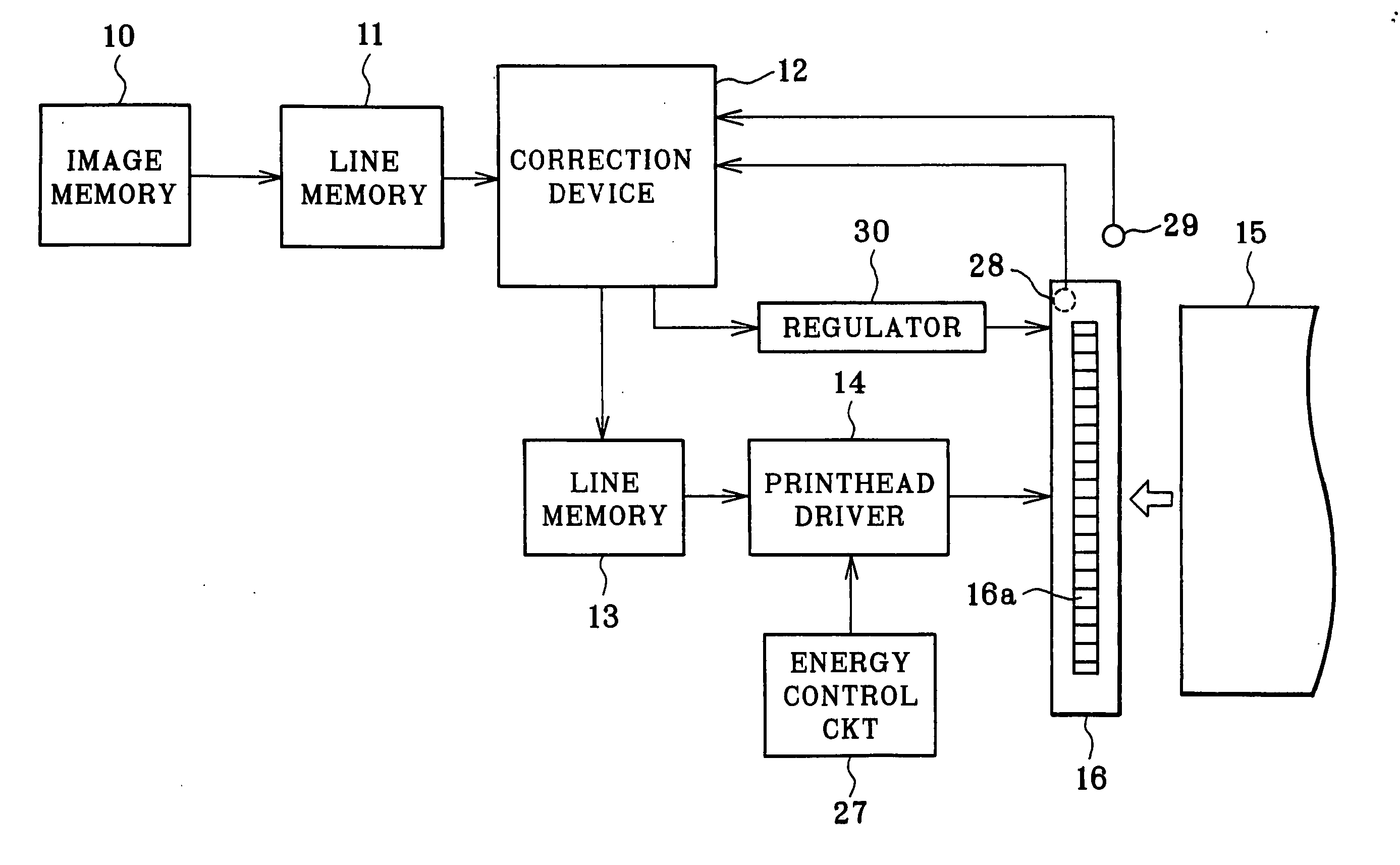
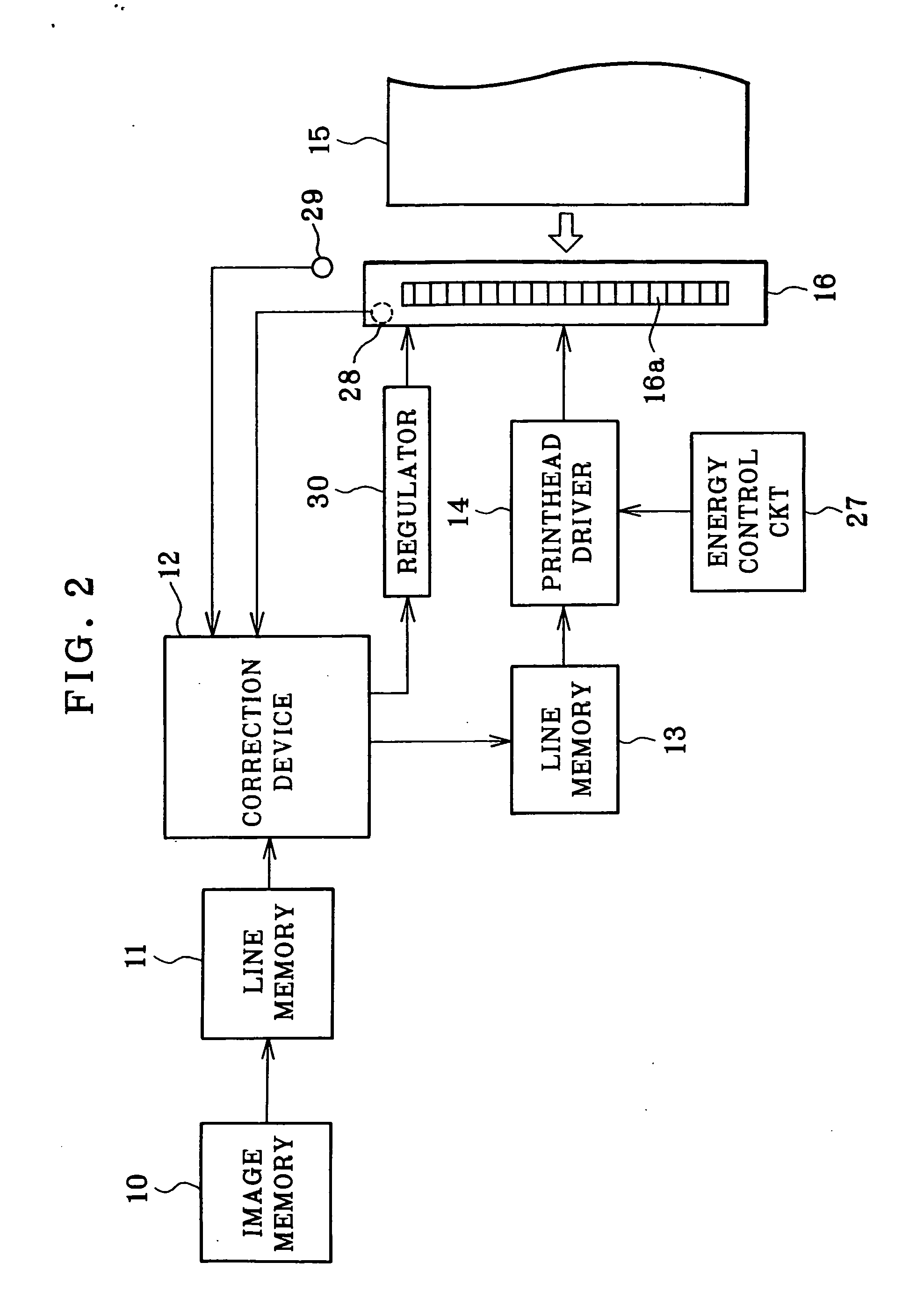
[0028] In FIG. 2, a color thermal printer of the invention is illustrated. Images to be printed are created and input by a digital camera, scanner, or other optical instruments. An image memory 10 of the printer stores the input images in forms of yellow, magenta and cyan image data. In the printing operation, image data are read from the image memory 10 by one line. A line memory 11 is connected, to which the image data is written to the line memory 11 by one line.

[0029] The image data of respective lines are read from the line memory 11. A correction device 12 is supplied with the image data of the lines. As will be described in detail, the image data is converted to initial heat data representing heat energy for coloring, and is subjected in the correction device 12 to correction of accumulated heat. After the correction, the heat data is converted to image data. A line memory 13 is connected, to which the image data is written.

[0030] A printhead driver 14 is connected with the...


PUM

PropertyMeasurementUnit
yellowaaaaaaaaaa
thicknessaaaaaaaaaa
heat accumulationaaaaaaaaaa

Abstract

A thermal head in a thermal printer has heating elements, a glaze layer and a ceramic board. Equations are used for correcting heat accumulation. Eg1(M+1,N)=(1−k1).E(M,N)+(1−k2).Eg1(M,N) Eg2(M+1,N)=k2(1−k3)(1−k4).Eg1(M,N) Ec1(M+1,N)=k2(1−k3).k4.Eg1(M,N)+(1−k5).Ec1(M,N) E(M,N): heat data of an Nth pixel of an Mth line after heat accumulation correction; Eg1(M,N): accumulated heat data of the glaze layer at point Pg1 and obtained in the correction of an (M−1)th line; Eg2(M,N): accumulated heat data of the glaze layer at point Pg2 and obtained in the correction of the (M−1)th line; Ec1(M,N): accumulated heat data of the ceramic board at point Pc1 and obtained in the correction of the (M−1)th line.

Description

BACKGROUND OF THE INVENTION [0001] 1. Field of the Invention [0002] The present invention relates to a heat accumulation correcting method, a thermal printer, and a computer-executable program. More particularly, the present invention relates to a heat accumulation correcting method used with a thermal printer for preventing an image quality from being degraded by accumulated heat of a heating element, and a thermal printer, and a computer-executable program. [0003] 2. Description Related to the Prior Art [0004] There are a direct thermal recording type of thermal printer and a thermal transfer recording type of thermal printer. The direct thermal recording heats a thermosensitive recording material with a thermal head to directly develop color. The thermal transfer recording heats the back side of an ink ribbon placed upon a recording material to transfer ink in the ink ribbon to a recording material. A thermal head has a number of heating elements disposed on a ceramic board. [000...

Claims


Application Information

Patent Timeline
Patent Type & Authority Applications(United States)
IPC IPC(8): B41J2/34
CPCB41J2/375
Inventor NAKATA, HAJIMEHASHIMOTO, TAKEAKI
Owner FUJIFILM HLDG CORP
Why Eureka
Try Eureka