Emitting light device for bicycles

a technology of emitting light and bicycle, which is applied in the direction of bicycle equipment, lighting and heating equipment, optical signals, etc., can solve the problems of dimming of illumination or related emitting light devices, and achieve the effect of short time and cost-effectiveness

Inactive Publication Date: 2006-10-19
WANG TSENG FAN +1
View PDF6 Cites 23 Cited by
  • Summary
  • Abstract
  • Description
  • Claims
  • Application Information

AI Technical Summary

Benefits of technology

[0017] As claim 3 claimed, in practice a chain, differential gears and chain wheels are combined to form a transmission mechanism, which can prevent the power from running off and let the power transferred more directly.

Problems solved by technology

Accordingly, in practice the warning signal of riding bicycle, illumination or related emitting light dev

Method used


Image

  • Emitting light device for bicycles
  • Emitting light device for bicycles
  • Emitting light device for bicycles

Examples


Embodiment Construction

[0023] The description is described in details according to the appended drawings hereinafter.

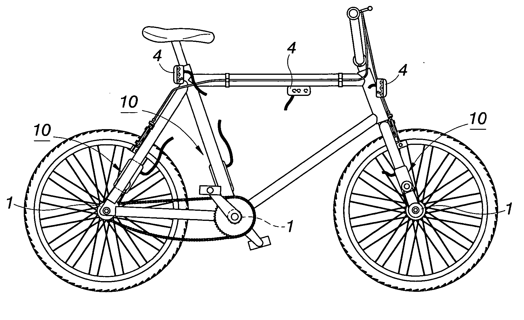
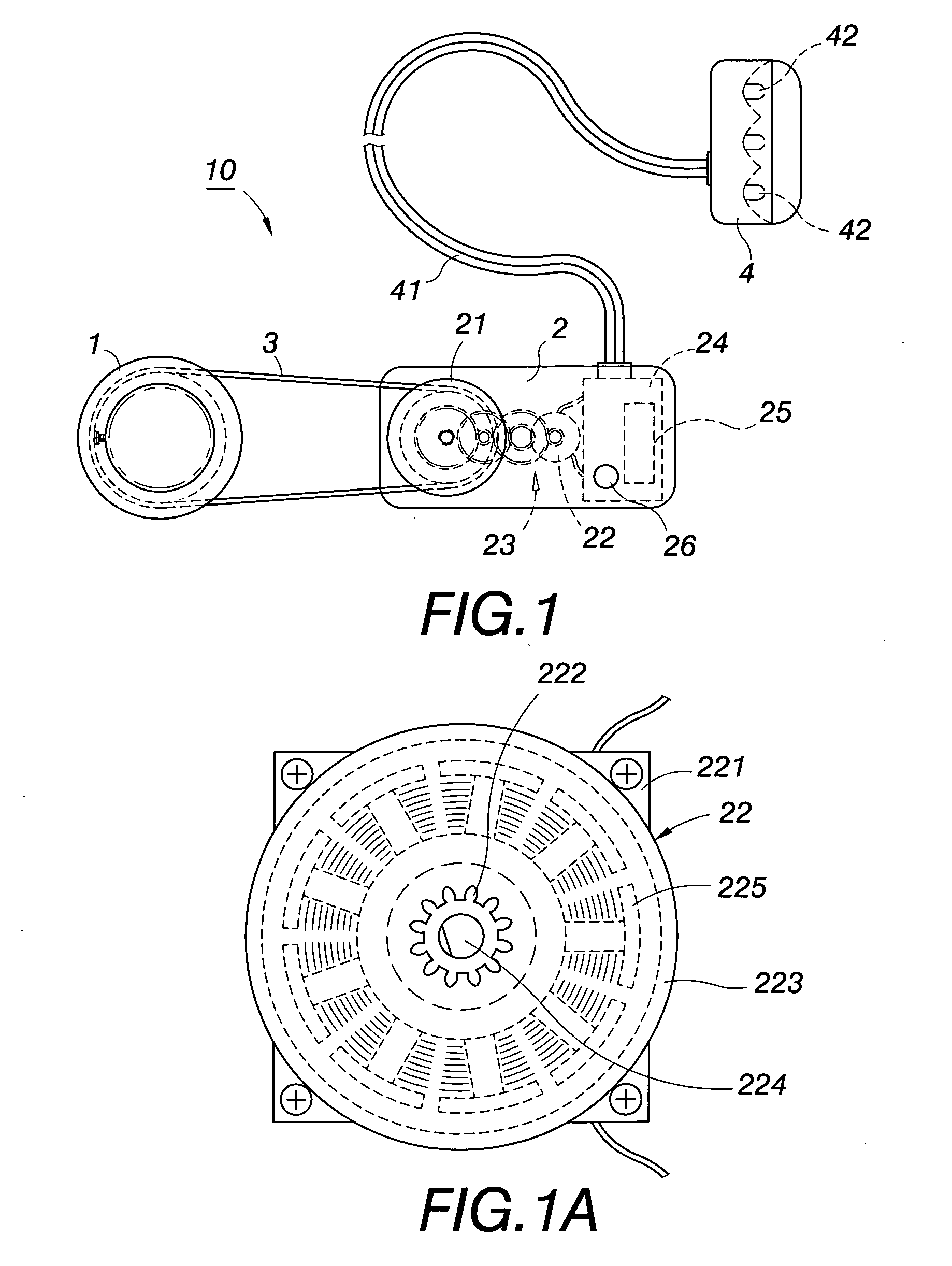
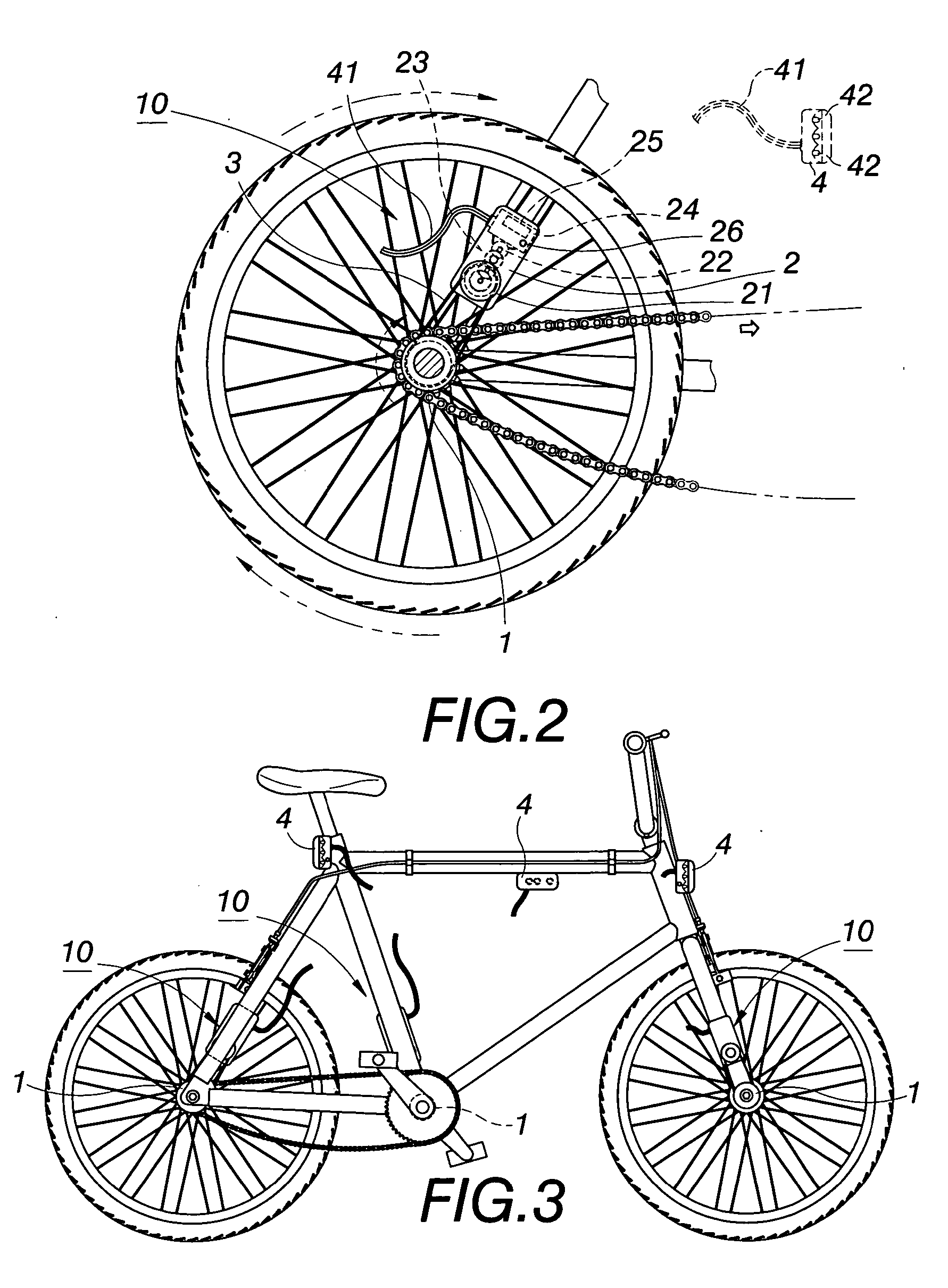
[0024] Referring to FIG. 1, a schematic view of the structure of an emitting light device of the present invention is shown. In that, an emitting light device 10 includes a driven wheel 1, a bicycle dynamo 2, a belt 3, and an emitting light base 4. Said bicycle dynamo 2 having an actuated wheel 21 disposed in itself, a dynamo 22, a set of differential gears 23 disposed between the actuated wheel and dynamo, a battery accumulator 25 (or a capacitor for a temporarily rechargeable electrification). Said belt 3 drives the driven wheel 1 and the actuated wheel 21, the belt 3 is designed as a transmission medium between them. Said emitting light base 4 has conducting cords 41 to connect to the PCB 24 of the bicycle dynamo 2. At least an LED 42 is disposed in the emitting light base 4 as the light source.

[0025] Referring to FIG. 1A, a schematic view of the structure of dynamo 22 is shown. In tha...


PUM


Abstract

An emitting light device of the present invention is realized on the bicycle to generate and conserve electric power, to light the emitting light device. In practice a driven wheel combined with rotating portion (i.e. rear wheel) of the bicycle to form a center-pivot type of axis-joint rotating structure. A bicycle dynamo includes 1. an actuated wheel and a dynamo with a set of differential gears between them, 2. a PCB, and 3. a battery accumulator. A transmission belt is rotated around the driven and actuated wheels; an emitting light base has conducting cords connected to PCB of the dynamo. As the driven wheel rotates, the actuated wheel is driven to rotate by the transmission belt. The speed ratio of transmission is changed by a set of differential gears to run the dynamo generate DC electricity and conserve electricity for battery. DC electricity can be applied to light LED.

Description

FIELD OF THE INVENTION [0001] The present invention is related to an emitting light device operated by a bicycle, particularly to a bicycle dynamo generates sufficient DC electricity to power an emitting base (i.e. handle bar stem head-lamp) emitting light by running on it's wheel, while the user rides bicycle. BACKGROUND OF THE INVENTION [0002] Generally speaking, warning signal head lamps or emitting light devices applied to bicycles can be categorized as following: [0003] 1. Passive warning signal device: consists of reflective clothing panel and reflective film sticker, the key component of them are high reflective glass bead, adverse reflecting incident lights cause very strong back reflective effects to glow a spotlight-like eye-catching warning signal intermittently. [0004] 2. Active warning signal device: includes bulb, LED, luminescent panel and luminescent plate, they can be classified as self-activated light sources, one of the key components of them is luminescent pigmen...

Claims


Application Information

Patent Timeline
IPC IPC(8): F21V33/00
CPCB62J6/10
Inventor WANG, TSENG-FANWANG, TSENG-HUANG
Owner WANG TSENG FAN
Why Eureka
Try Eureka