Vibration-sound generating device and yoke thereof

a technology of vibration-sound and generating device, which is applied in the direction of mechanical vibration separation, dynamo-electric machines, fibre diaphragms, etc., can solve the problems of poor performance limited volume of magnets, and insufficient suspension and yoke of conventional vibration-sound devices to generate desired sufficient vibration. , to achieve the effect of improving the performance of vibration and speaker

Inactive Publication Date: 2006-10-19
SAMSUNG ELECTRO MECHANICS CO LTD
View PDF5 Cites 21 Cited by
  • Summary
  • Abstract
  • Description
  • Claims
  • Application Information

AI Technical Summary

Benefits of technology

[0009] The present invention provides vibration-sound generatin

Problems solved by technology

But the mass of the suspension and yoke of the conventional vibration-sound device is not high enough to generate desired sufficient vibration.
But the conventional art which fabricates an extra poise and attaches it to the periphery of the yoke not only requires an additional process of attachment of the poise but also brings about a possibility of contact between the magnetic vibration part and the v

Method used


Image

  • Vibration-sound generating device and yoke thereof
  • Vibration-sound generating device and yoke thereof
  • Vibration-sound generating device and yoke thereof

Examples


first embodiment

[0023] Reference will now be made in detail to the embodiments of the present general inventive concept, examples of which are illustrated in the accompanying drawings, wherein like reference numerals refer to the like elements throughout. The embodiments are described below in order to explain the present general inventive concept by referring to the figures.

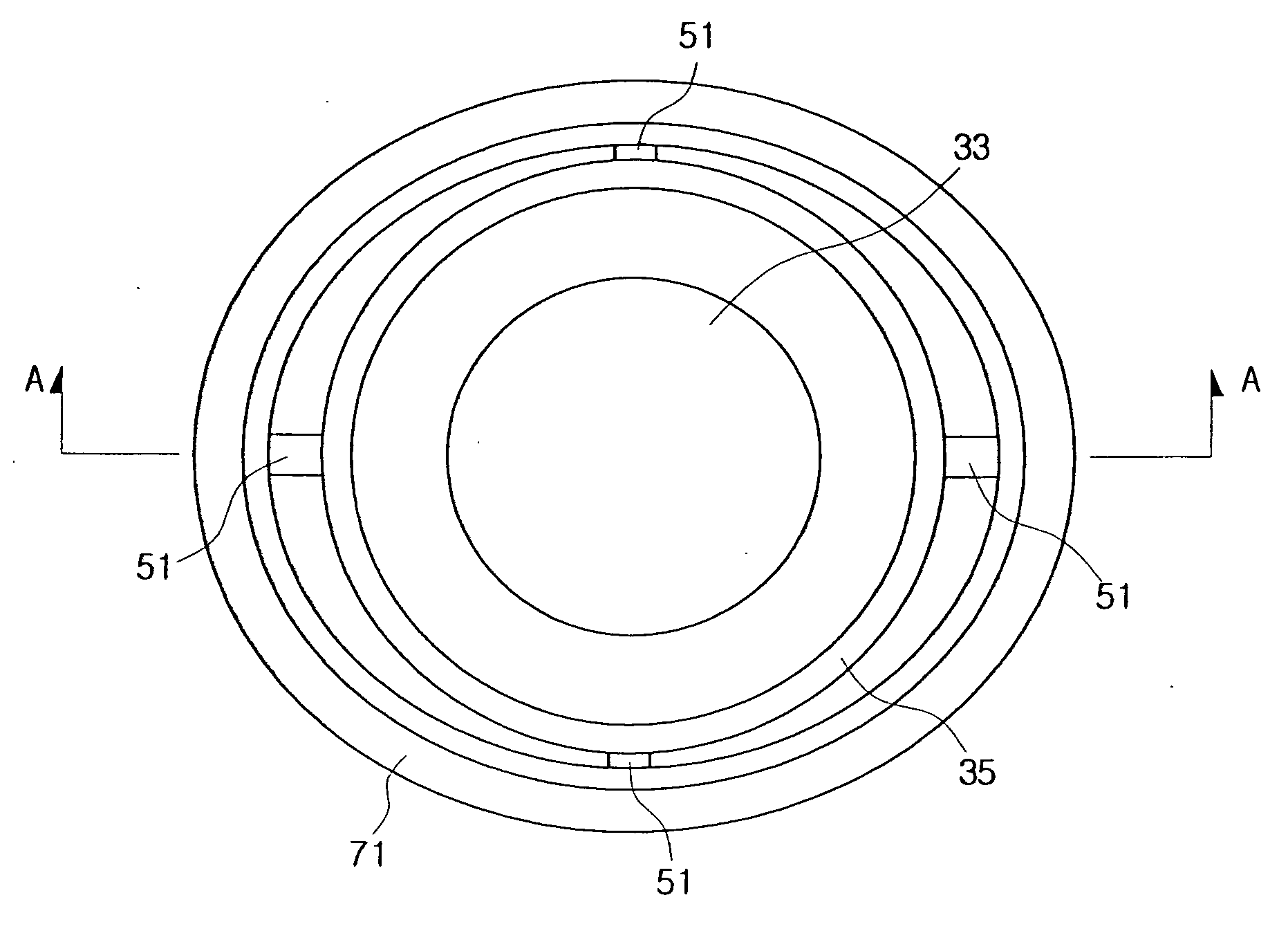
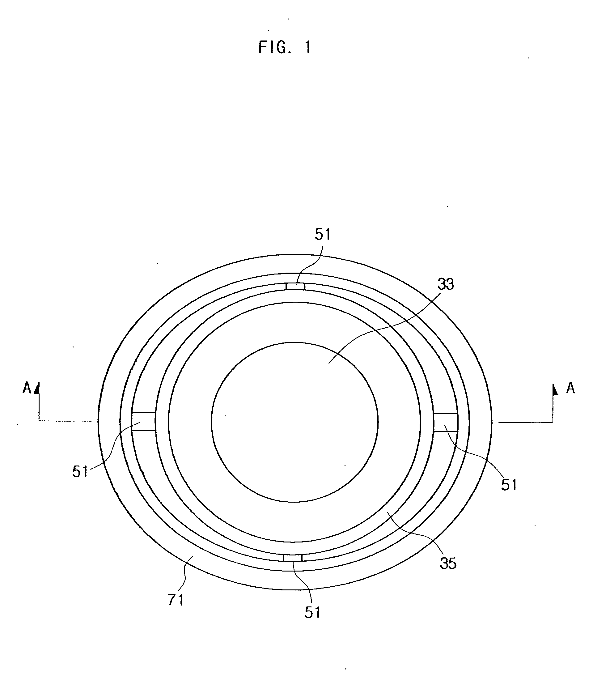
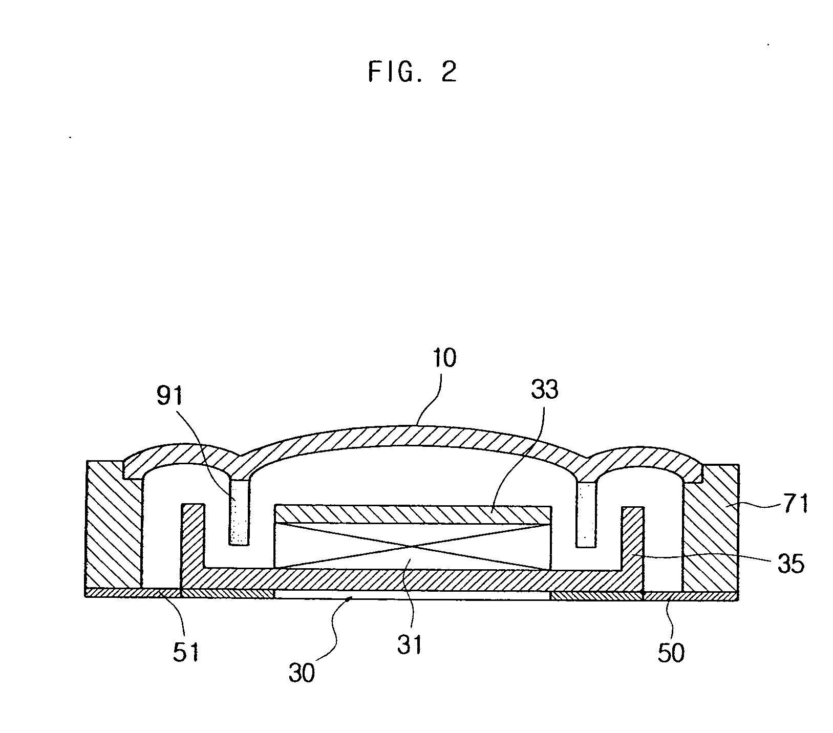
[0024]FIG. 1 is a plane view illustrating inner structure of a vibration-sound generating device according to one embodiment of the present invention and FIG. 2 is a sectional view on the line of AA′ as illustrated in FIG. 1. The vibration-sound generating device of one embodiment of the present invention comprises a diaphragm 10, a vibration part 30, a suspension 50, a supporting part 71, and a voice coil 91.

[0025] Referring to FIG. 2, the diaphragm 10 is attached on upper surface of the supporting part 71. The diaphragm 10 is formed of titan or polycarbonate and has a thickness of 10 μm-50 μm. The diaphragm 10 attached to t...

second embodiment

[0046] Referring to the FIG. 6, the vibration-sound generating device of another embodiment of the present invention comprises the diaphragm 10, a vibration part 30′, the suspension 50, the supporting part 71, the voice coil 91, and a vibration coil 93. The diaphragm 10, suspension 50, supporting part 71 and voice coil 90 have same structure and function to the above embodiment; the following will explain the vibration part 30′ and vibration part 93.

[0047] As illustrated in FIG. 6, the vibration part 30′ comprises a magnet 31′, a upper yoke 33′ and a lower yoke 35′. The magnet 31′ has a donut shape, and the upper and lower surface on which the upper yoke 33′ and lower yoke upper 35′ are attached respectively.

[0048] The upper yoke 33′ is supported elastically to the supporting part 71 by the suspension 50. The lower yoke 35′ attached to the magnet 31′ is mounted on the lower surface of the suspension 50. The voice coil 91 is attached to the lower surface of the diaphragm 10 and pro...


PUM


Abstract

A vibration-sound generating device and yoke thereof are described. The vibration-sound generating device comprises a diaphragm, a vibration part comprising a magnet and a yoke, which is positioned apart from the diaphragm by a desired distance, a suspension elastically supporting the vibration part, a supporting part supporting the diaphragm and the suspension, and a voice coil electromagnetically driving the diaphragm and the vibration part. The yoke of the invention has higher specific gravity and magnetic permeability than iron. So that it can improve performance of vibration and sound device.

Description

CROSS-REFERENCE TO RELATED APPLICATIONS [0001] This application claims the benefit of Korean Patent Application No. 2005-31490 filed with the Korea Industrial Property Office on Apr. 15, 2005, the disclosure of which is incorporated herein by reference. BACKGROUND OF THE INVENTION [0002] 1. Field of the Invention [0003] This document relates to a vibration-sound generating device and yoke thereof and more particularly, a vibration-sound generating device and yoke thereof having improved vibration and sound performance. [0004] 2. Description of the Related Art [0005] Recently, the release of mobile terminal, such as cellular phone or PDA, having camera and sound performance is increased rapidly. Accordingly, the needs for smaller mobile terminal is increasing, the use of vibration-sound device, which integrates a vibration motor, a receiver and a speaker so as to decrease in size and manufacturing price of the mobile terminal is augmented. Such vibration-sound devices according to th...

Claims


Application Information

Patent Timeline
IPC IPC(8): H04R9/06
CPCB06B1/045H02K33/18H04R9/025H04R2400/03H04R2307/027H04R2307/029H04R2209/024H04R2307/025
Inventor CHUNG, SEUK-HWANCHOI, JUN-KUNKIM, SANG-WONKIM, SEONG-GEUNPARK, SEOK-JUN
Owner SAMSUNG ELECTRO MECHANICS CO LTD
Why Eureka
Try Eureka