Eureka AIR delivers breakthrough ideas for toughest innovation challenges, trusted by R&D personnel around the world.

Vehicle position recognizing device and vehicle position recognizing method

Inactive Publication Date: 2006-10-19
AISIN AW CO LTD +1
View PDF4 Cites 73 Cited by
  • Summary
  • Abstract
  • Description
  • Claims
  • Application Information

AI Technical Summary

Benefits of technology

[0010] Accordingly, it is an object of the present invention to provide a vehicle position recognition apparatus and a vehicle position recognition method which enable the position of the vehicle on the road being traveled to be more accurately pinpointed by using map information, vehicle information, and the like, in addition to the image information picked up by an imaging device mounted on the vehicle.

Problems solved by technology

However, the precision of pinpointing the position of a vehicle using the GPS has a margin of error on the order of tens of meters, so that it has been difficult to pinpoint position with greater precision.
However, with the system of the related art discussed above, while a determination can be made as to whether or not the road on which the vehicle is traveling is an expressway, the position of the vehicle on the road being traveled, for example, when the vehicle is traveling on a road having multiple lanes in the direction of traffic, is impossible to pinpoint in the transverse dimension (width) of the road.
Thus, identification of the lane traveled by the vehicle is unreliable.

Method used


Image

  • Vehicle position recognizing device and vehicle position recognizing method
  • Vehicle position recognizing device and vehicle position recognizing method
  • Vehicle position recognizing device and vehicle position recognizing method

Examples


first embodiment

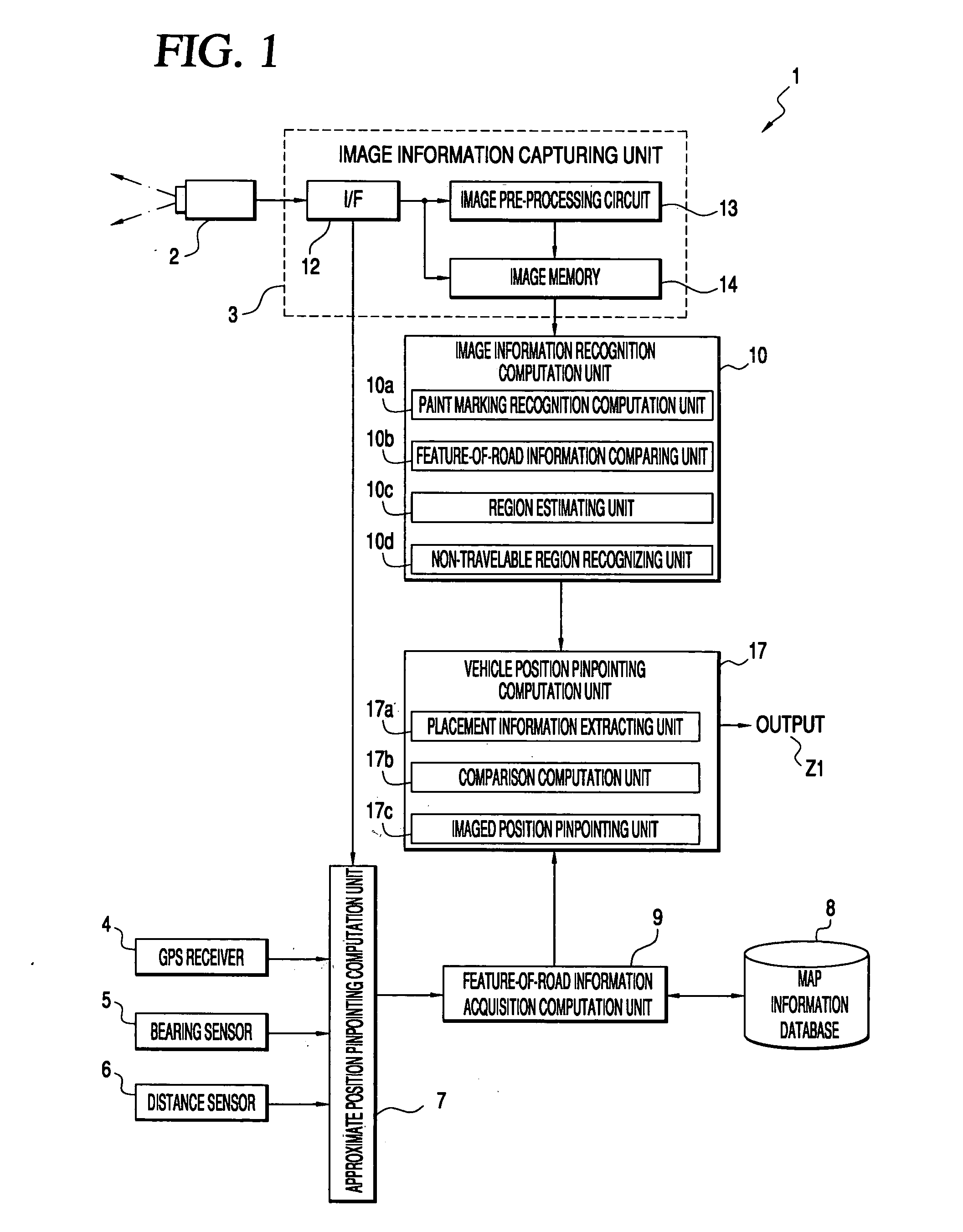
[0053] A first embodiment of the present invention will be described with reference to FIG. 1.

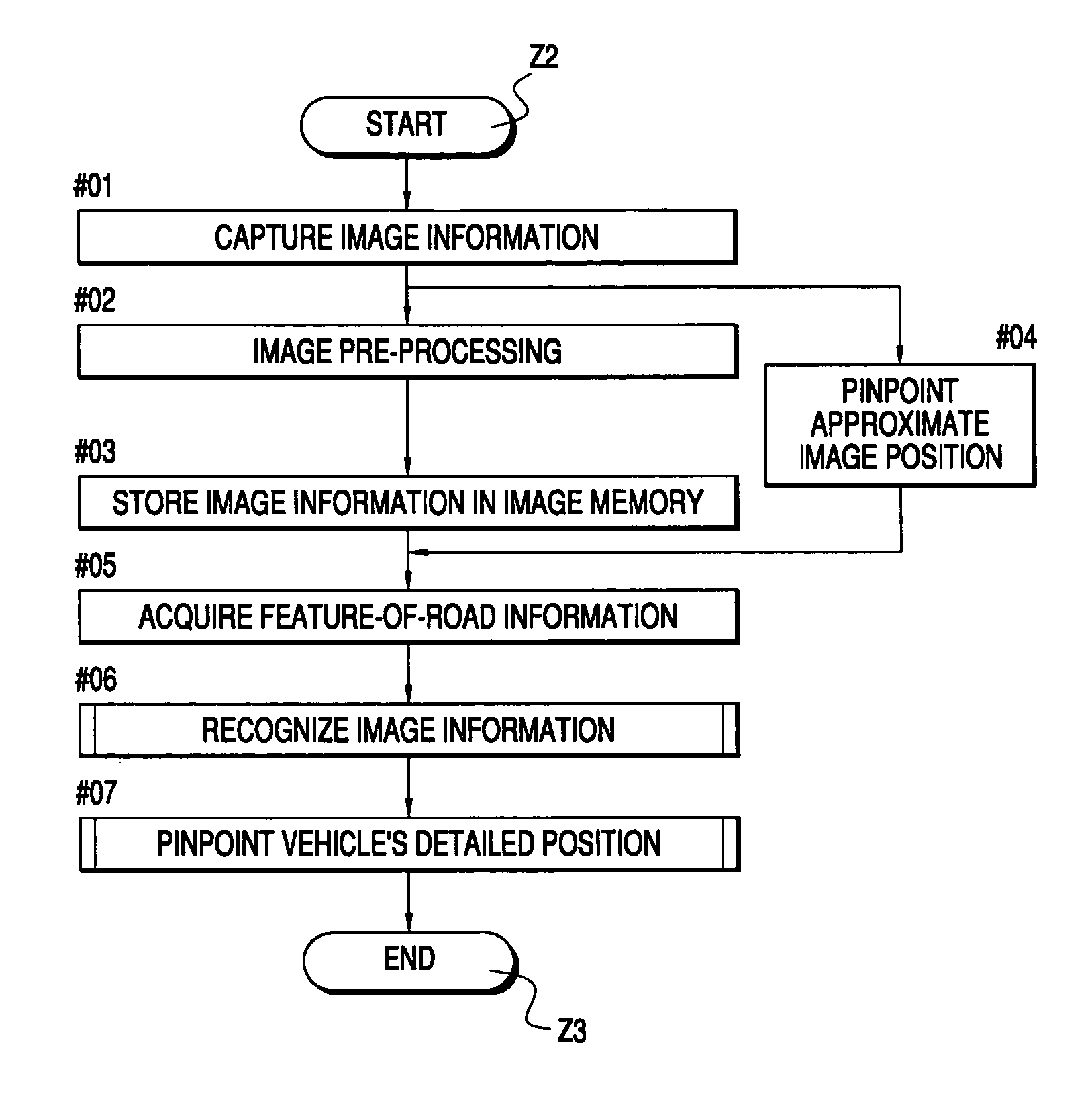
[0054] The vehicle position recognition apparatus 1 according to the first embodiment executes processing for pinpointing the position of vehicle M on a road 11, i.e., the position pinpointed relative to width and length of the road, based on the image results of recognition processing of the image information picked up with an imaging device 2, and feature-of-road information C obtained from stored map information.

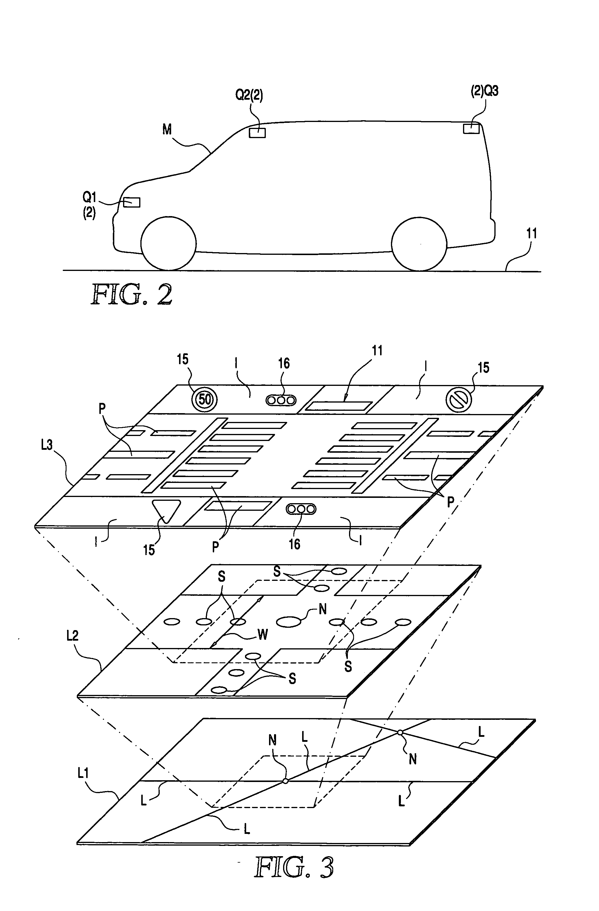
[0055] As shown in FIG. 1, the vehicle location recognition apparatus 1 of the first embodiment includes an image information capturing unit 3 for capturing image information G from the imaging device 2 mounted on the vehicle M (see FIG. 2), a GPS (Global Positioning System) receiver 4, position approximation unit 7 for approximating the location of the area imaged with the imaging device 2, based on the output from a bearing sensor 5 and a distance sensor 6, a feature-of-road ...

second embodiment

[0120] Next, a second embodiment of the present invention will be described with reference to FIG. 13 which is a block diagram of the hardware of a vehicle position recognition apparatus 1 according to the present invention.

[0121] The vehicle position recognition apparatus 1 according to this second embodiment is different from the above-described first embodiment in that the feature-of-road information acquisition unit 9 acquires the feature-of-road information C, relating to the ground objects around the imaged position of the image information G, from map information stored in the form of classified-by-lane feature-of-road information C′, with multiple positions different for each lane of the road 11 as reference points. The lane position of the vehicle M is pinpointed by comparing each of the thus classified reference points, i.e. feature-of-road information C′ with the location (position) of the ground object within the image information G.

[0122] Also, the vehicle position re...


PUM


Abstract

A vehicle position recognition apparatus includes an image information capturing unit for capturing image information for at least the surface of a road picked up by an imaging device mounted on the vehicle; a feature-of-road information acquiring unit for acquiring information identifying ground objects around the imaged position from stored map information; an image information recognizing unit for recognition of images corresponding to the ground objects included in the image information; and a vehicle position pinpointing unit for pinpointing the position of the vehicle transverse of the road based on the acquired feature-of-road information and the position of the image of the ground object in the image formation which has been recognized by the image information recognizing unit.

Description

INCORPORATION BY REFERENCE [0001] The disclosure of Japanese Patent Application No. 2005-021338 filed on Jan. 28, 2005, including the specification, drawings and abstract thereof, is incorporated herein by reference in its entirety. BACKGROUND OF THE INVENTION [0002] 1. Field of the Invention [0003] The present invention relates to a vehicle position recognition apparatus and to a vehicle position recognizing method for recognizing the image of a predetermined object in the image information obtained in real time, and for pinpointing the position of the vehicle in the width-of-road direction. [0004] 2. Description of the Related Art [0005] In recent years navigation devices have employed signals from the GPS (Global positioning system) to pinpoint the position of a moving vehicle. However, the precision of pinpointing the position of a vehicle using the GPS has a margin of error on the order of tens of meters, so that it has been difficult to pinpoint position with greater precision...

Claims


Application Information

Patent Timeline
IPC IPC(8): G06K9/00G06T17/05
CPCG06T7/0042G06K9/00798G06T17/05G06T7/73G06V20/588G01C21/26
Inventor MIYAJIMA, TAKAYUKINAKAMURA, MASAKINAKAMURA, MOTOHIRO
Owner AISIN AW CO LTD
Why Eureka
Eureka Blog
Learn More