Use of recirculated exhaust gas in a burner-based exhaust generation system for reduced fuel consumption and for cooling

a technology of exhaust gas simulation and combustion engine, which is applied in the direction of combustion types, lighting and heating apparatus, instruments, etc., can solve the problems of engine-based systems that are inconsistent, maintenance intensive, and expensive to opera

Active Publication Date: 2006-10-19
SOUTHWEST RES INST
View PDF99 Cites 28 Cited by
  • Summary
  • Abstract
  • Description
  • Claims
  • Application Information

AI Technical Summary

Problems solved by technology

As a result of recent regulatory initiatives, motor vehicle emissions aftertreatment devices are required to have longer useful lives.
This requirement places severe demands on emissions control devices as they age.
However, engine-based systems can be inconsistent, maintenance intensive, and expensive to operate.
I...

Method used


Image

  • Use of recirculated exhaust gas in a burner-based exhaust generation system for reduced fuel consumption and for cooling
  • Use of recirculated exhaust gas in a burner-based exhaust generation system for reduced fuel consumption and for cooling
  • Use of recirculated exhaust gas in a burner-based exhaust generation system for reduced fuel consumption and for cooling

Examples


Embodiment Construction

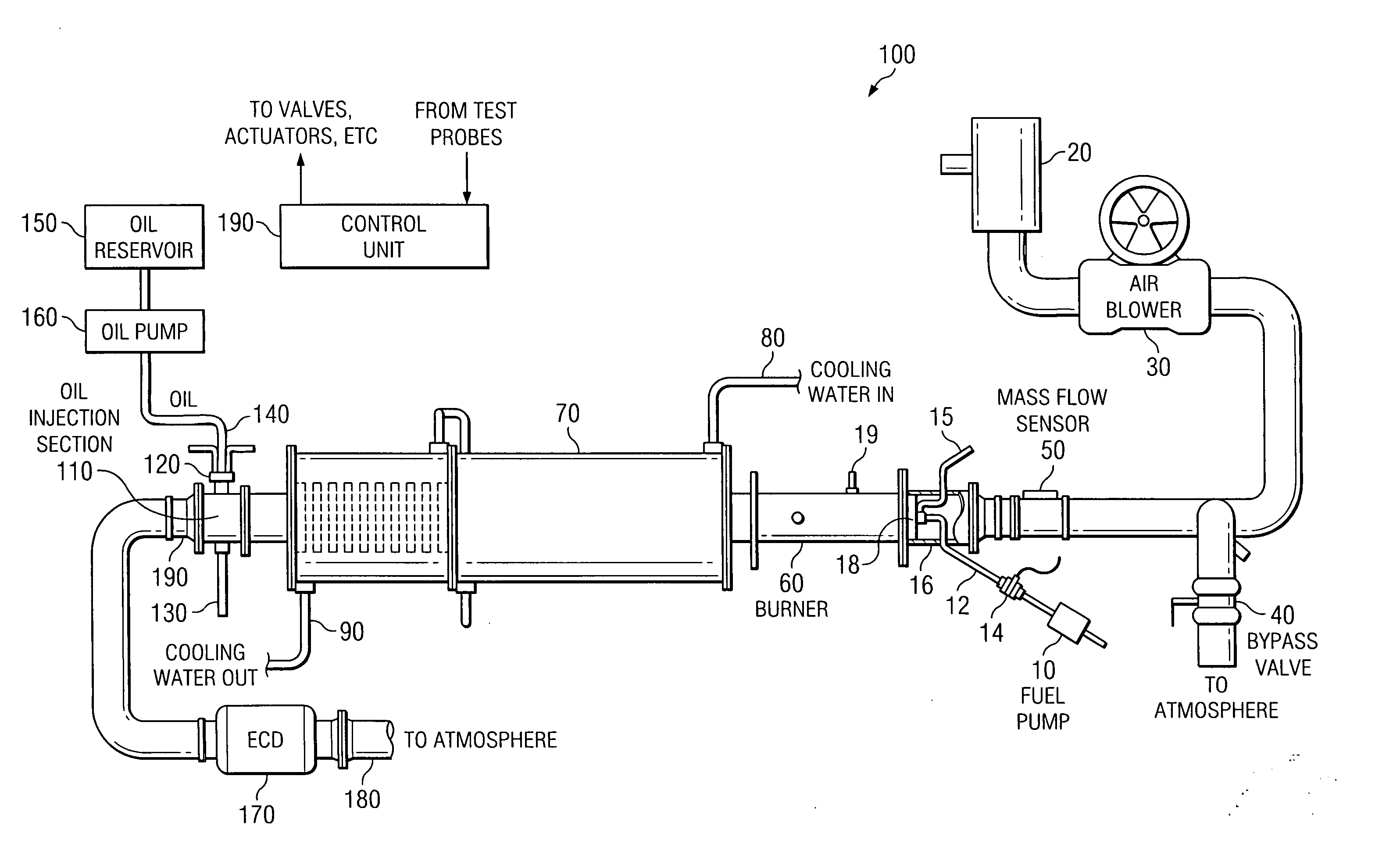
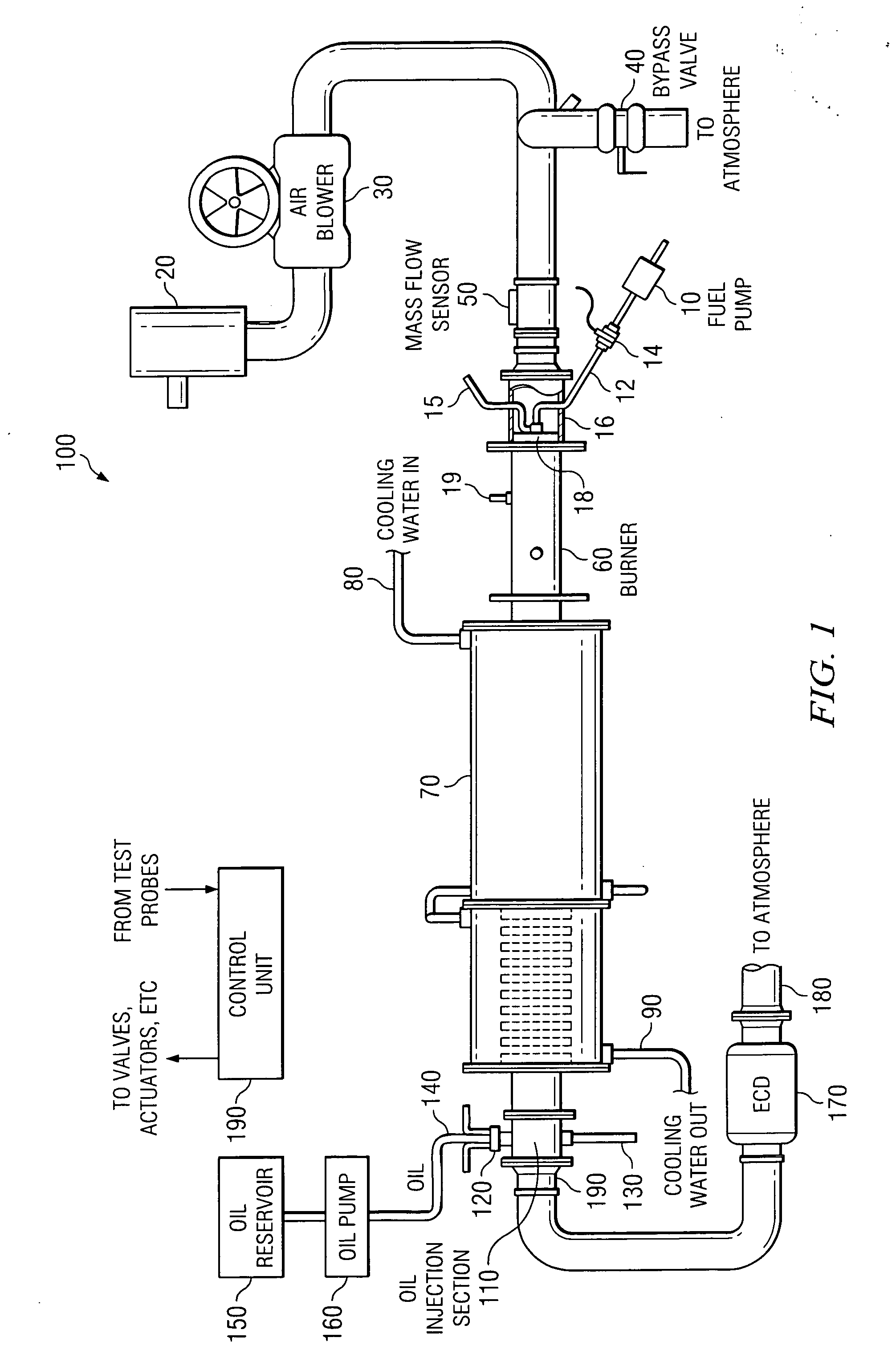
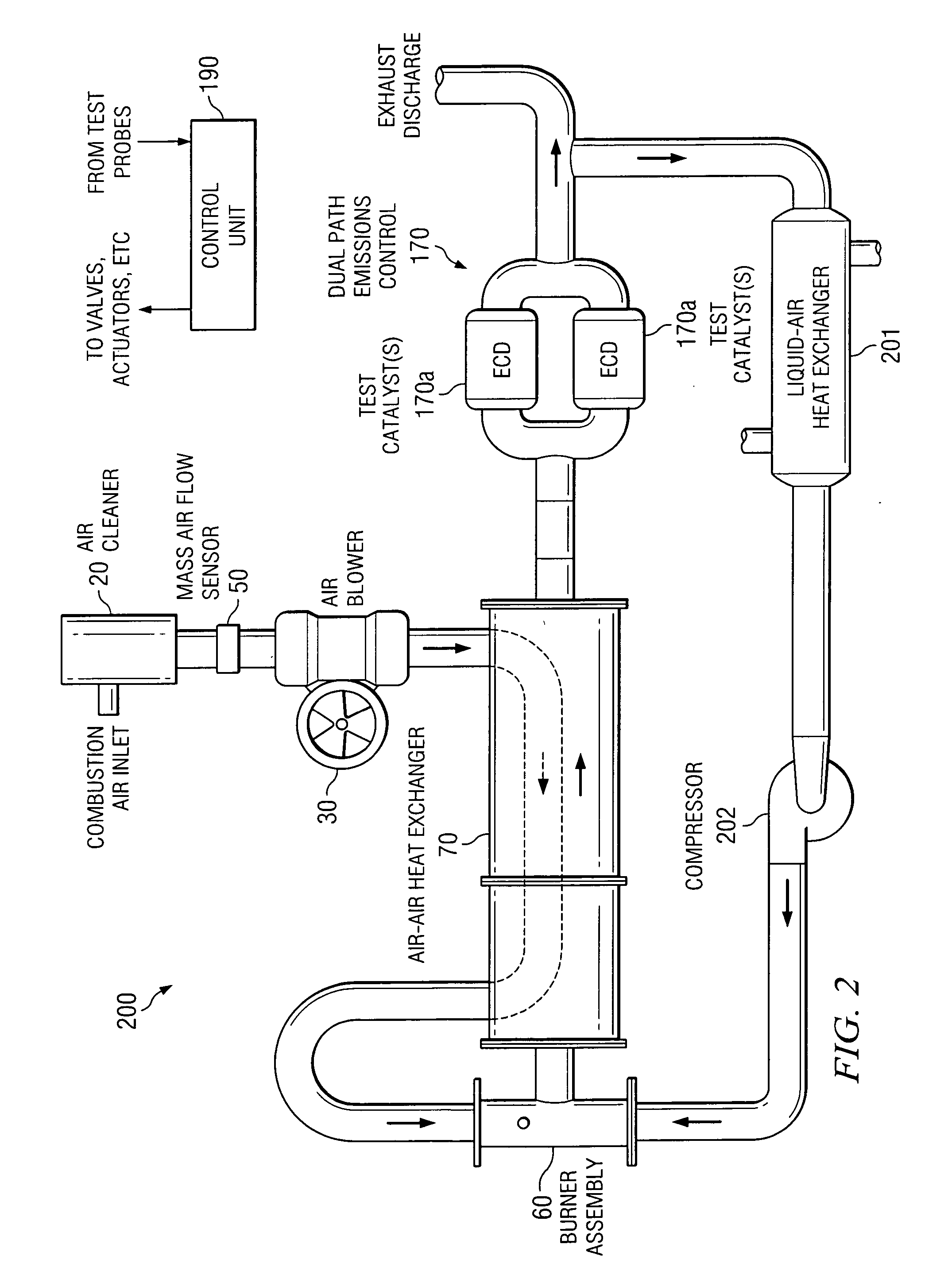
[0011] The following description is directed to various embodiments of a burner-based exhaust gas generation system, in which exhaust gas is diverted from the main exhaust path and recirculated back to a more upstream point in the path. In the embodiments of this description, the system is used for aging emissions control devices (ECD's). A portion of the exhaust gas is diverted from the main exhaust path downstream the burner, a heat exchanger, and test ECD's. It is re-circulated such that it re-enters the main exhaust path after the burner.

[0012] Overview of Burner-Based Exhaust Gas Generation System

[0013]FIG. 1 illustrates a burner-based exhaust gas generation system 100. System 100 is an example of a system with which the invention (described in connection with FIGS. 2-4) may be used.

[0014] System 100 may be used to simulate the production of exhaust gas by an internal combustion engine. For example, it may be used to simulate the production of exhaust gas by a motor vehicle....


PUM


Abstract

A burner-based exhaust gas generation system, for producing exhaust gas, typically for use in testing exhaust system devices. Post-burner exhaust gas is recirculated back to a main exhaust line, and used for purposes such as cooling or enhancing the burner output.

Description

CROSS-REFERENCE TO RELATED APPLICATIONS [0001] This application claims the benefit of U.S. Provisional Application No. 60 / 662,581 filed on Mar. 17, 2005, entitled “Use of Recirculated Exhaust Gas in a Burner-Based Exhaust Generation System for Reduced Fuel Consumption and for Cooling”, which is incorporated herein by reference in its entirety.TECHNICAL FIELD OF THE INVENTION [0002] This invention relates generally to systems and methods for simulating exhaust gas produced by an internal combustion engine, and more particularly to recycling exhaust gas in a burner-based exhaust gas simulation system for purposes such as reducing fuel consumption and cooling. BACKGROUND OF THE INVENTION [0003] As a result of recent regulatory initiatives, motor vehicle emissions aftertreatment devices are required to have longer useful lives. For example, in the 1990's, the United States Environmental Protection Agency (EPA) increased the mileage for which automotive emission control elements must fun...

Claims


Application Information

Patent Timeline
IPC IPC(8): F23G7/08F23M3/00
CPCF23C9/00F23C2202/30F23D11/00F23L2900/00001F23J15/06F23L5/02F23L15/04F23D2206/00Y02E20/34
Inventor BURRAHM, ROBERT WAYNEROSS, MICHAEL GLENNWEBB, CYNTHIA CHAFFINTIMMONS, SUZANNE ANNETTEBARTLEY, GORDON JAMES JOHNSTON
Owner SOUTHWEST RES INST
Why Eureka
Try Eureka