Ultra wideband radio transmitter, ultra wideband radio receiver, and ultra wideband radio communication method

a radio transmitter and receiver technology, applied in the field of ultra wideband radio transmitters, ultra wideband radio receivers and ultra wideband radio communication methods, can solve the problems of inability to obtain a theoretical transfer rate undesirably, and the antenna size of such a wideband signal is inevitable to increase, so as to achieve a miniaturized antenna and secure higher transfer rate and communication quality.

Inactive Publication Date: 2006-10-19
SAMSUNG ELECTRONICS CO LTD
View PDF10 Cites 20 Cited by
  • Summary
  • Abstract
  • Description
  • Claims
  • Application Information

AI Technical Summary

Benefits of technology

[0014] The present invention has been made under these circumstances, and it is therefore an object of the present invention to provide an ultra wideband radio transmitter, an ultra wideband radio receiver and an ultra wideband radio communication method capable of securing higher transfer rate and communication quality than conventional ones while avoiding a band where communication signals are densely concentrated, and also capable of miniaturizing an antenna.

Problems solved by technology

It is known that since a signal level of the WLAN is very higher than that of a UWB signal, this becomes the cause of interference to UWB communication, causing deterioration of BER (Bit Error Rate) during communication.
Therefore, when communication is performed in a frequency band including the 5 GHz band, it is not possible to obtain a theoretical transfer rate undesirably.
In addition, an antenna for such a wideband signal is inevitably theoretically increased in size.

Method used


Image

  • Ultra wideband radio transmitter, ultra wideband radio receiver, and ultra wideband radio communication method
  • Ultra wideband radio transmitter, ultra wideband radio receiver, and ultra wideband radio communication method
  • Ultra wideband radio transmitter, ultra wideband radio receiver, and ultra wideband radio communication method

Examples


first embodiment

[0057] an ultra wideband radio transceiver according to the present invention will now be described with reference to the accompanying drawings.

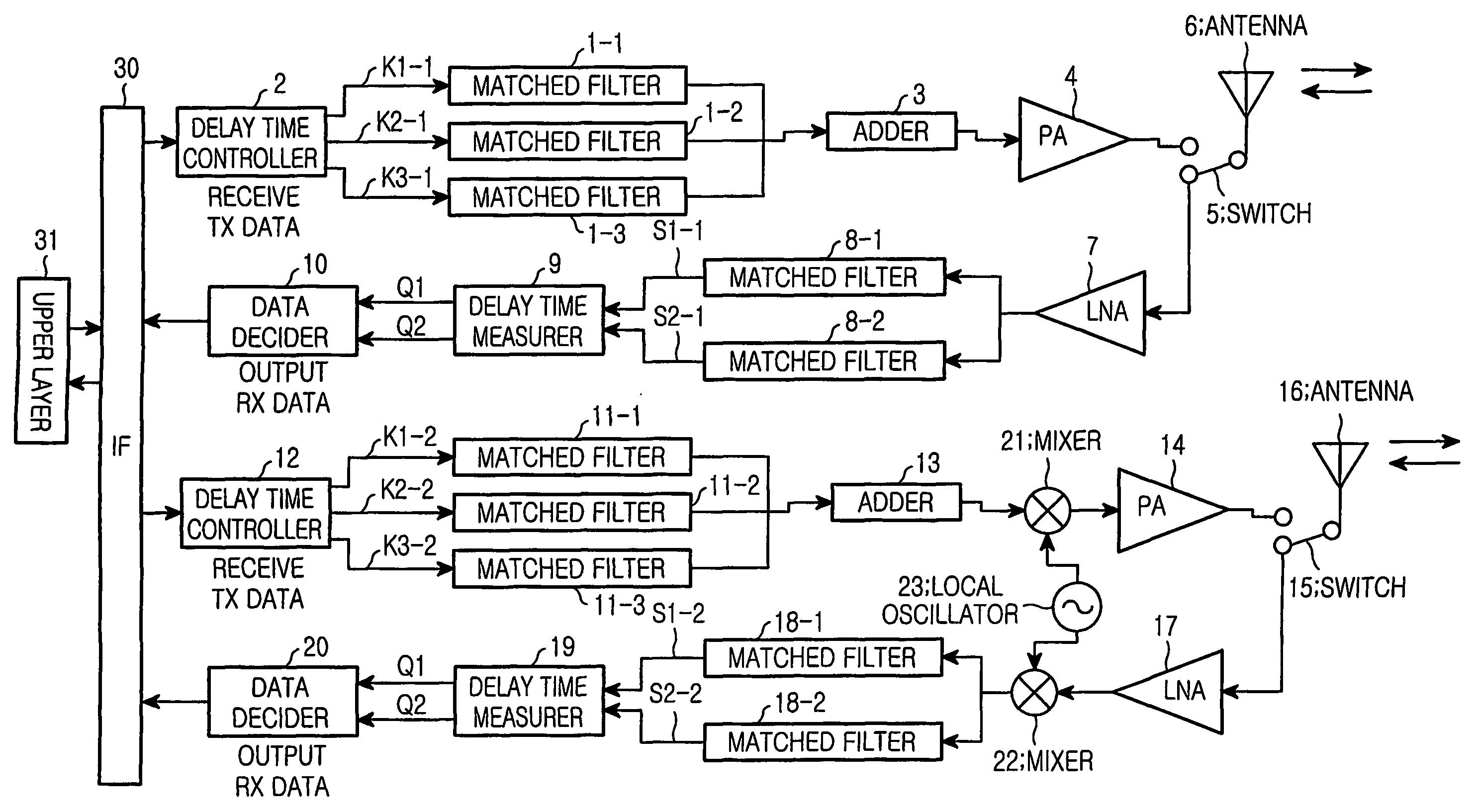
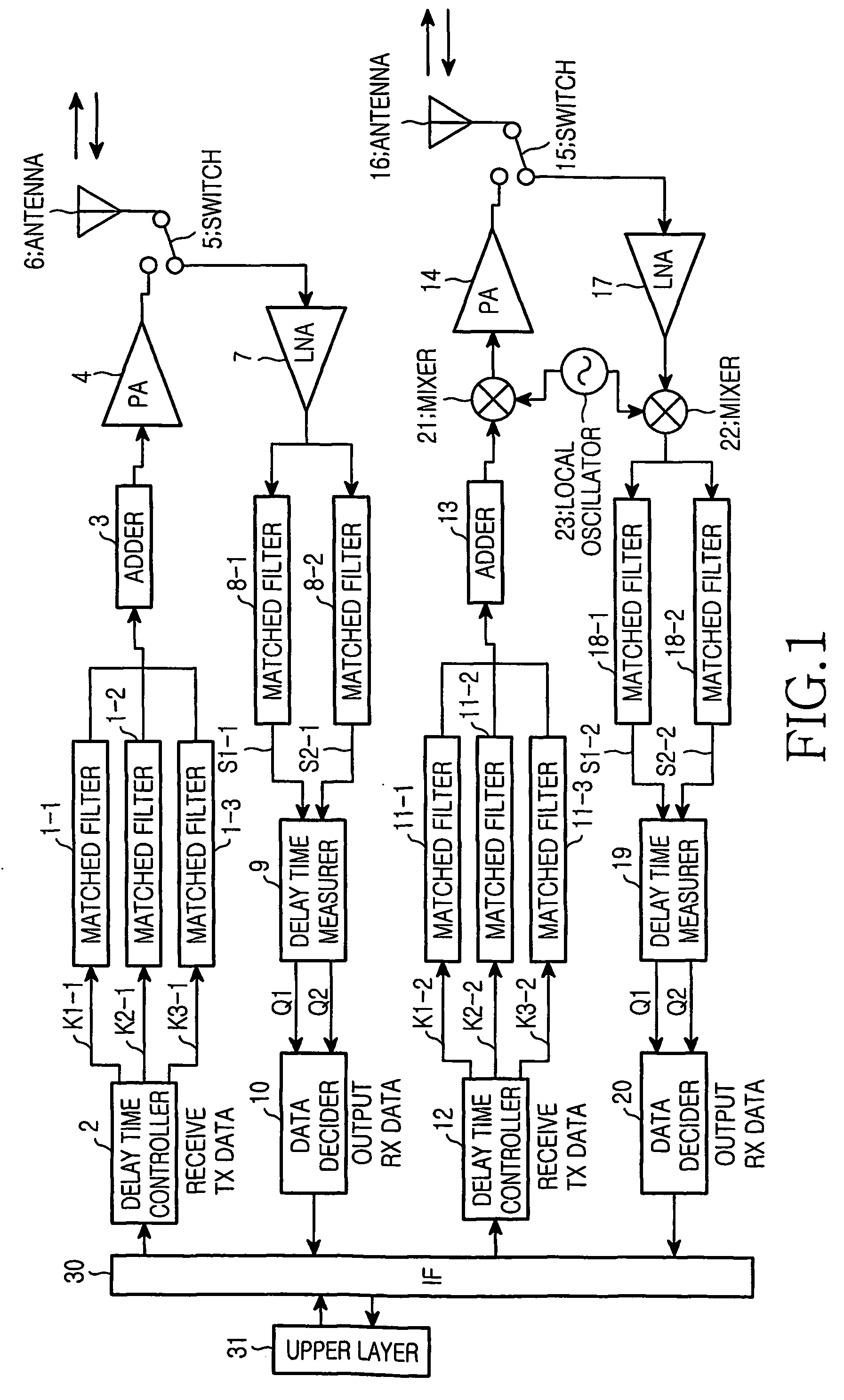
[0058]FIG. 1 is a diagram illustrating a structure of an ultra wideband radio transceiver according to an embodiment of the present invention. An ultra wideband radio transceiver according to this embodiment is comprised of first and second transmitters, first and second receivers, an interface (IF) 30, and an upper layer 31.

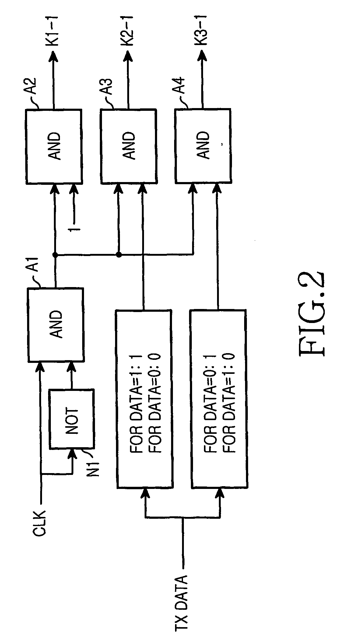
[0059] The first transmitter is comprised of matched filters 1-1 to 1-3, a delay time controller 2, an adder 3, a power amplifier (hereinafter referred to as “FA”) 4, a switch 5, and an antenna 6.

[0060] The first receiver is comprised of the switch 5 (shared with the first transmitter), the antenna 6 (also shared with the first transmitter), a low-noise amplifier (hereinafter referred to as “LNA”) 7, matched filters 8-1 and 8-2, a delay time measurer 9, and a data decider 10.

[0061] The second transmitter is formed by ...

second embodiment

[0145] Next, with reference to the drawings, a description will be made of the ultra wideband radio transceiver applied to the ultra wideband radio transmitter and receiver according to the present invention. FIG. 29 is a diagram illustrating a structure of an ultra wideband radio transceiver according to this embodiment.

[0146] The ultra wideband radio transceiver according to this embodiment is different from that of the first embodiment in that PA 4 and PA 14; switch 5 and switch 15; antenna 6 and antenna 16; and LNA 7 and LNA 17 are unified.

[0147] Now, a description will be made of only the difference between the ultra wideband radio transceiver according to this embodiment and that of the first embodiment, and a description of the overlapped parts will be omitted for simplicity.

[0148] The ultra wideband radio transceiver of FIG. 29 according to this embodiment, like that of the first embodiment, is comprised of first and second transmitters, first and second receivers, an inte...


PUM


Abstract

Disclosed are ultra wideband radio transmitter, ultra wideband radio receiver, and ultra wideband radio communication method capable of securing higher transfer rate and communication quality than conventional ones while avoiding a band where communication signals are concentrated, and capable of miniaturizing an antenna. In a transmitter, a delay time controller (12) outputs a periodic pulse to matched filters 11-1 and 11-2 when transmission data is 1, and outputs the periodic pulse to matched filters 11-1 and 11-3 when the transmission data is 0. The matched filter 11-1 outputs reference signal, the matched filter 11-2 outputs first data signal ahead of the reference signal, and the matched filter 11-3 outputs second data signal behind the reference signal. An adder (13) adds up these, a mixer (21) frequency-converts output of the adder using a local signal received from a local oscillator (23), and an antenna (6) radiates output of the mixer (21).

Description

FIELD OF THE INVENTION [0001] The present invention relates generally to an ultra wideband radio transmitter, an ultra wideband radio receiver and an ultra wideband radio communication method using an ultra wideband used in connecting a PDA (Personal Digital Assistant), a portable phone and a peripheral device in a wireless LAN (Local Area Network) or PAN (Personal Area Network). DESCRIPTION OF THE RELATED ART [0002] An ultra wideband radio communication scheme that spreads data over a very wide frequency band of about 1 GHz and overlays the data on a pulse without using a carrier during transmission and reception attracts public attention as a new data communication scheme for spread spectrum communication [see Non-patent Reference 1]. [0003] Since data transmitted at each frequency band has as low power as noises, the ultra wideband radio communication scheme is advantageous in that it does not interfere with a radio apparatus using the same frequency band and has low power consum...

Claims


Application Information

Patent Timeline
Patent Type & Authority Applications(United States)
IPC IPC(8): H04M1/00H04B1/707H04B1/04H04B1/18H04B1/28H04B1/40H04B1/7183H04B7/00H04L25/03
CPCH04B1/28H04B1/692H04L25/03834H04B1/7174H04B1/71637H04B1/04H04B1/18H04B7/00H04B1/40
Inventor NAGASAKA, HIROYUKI
Owner SAMSUNG ELECTRONICS CO LTD
Why Eureka
Try Eureka